I'm powering a project with a 2-cell 7.4V LiPo battery. What circuit do I add to make the unit stop drawing power when the voltage from the battery drops below 6.4V? The goal is to protect the LiPo battery from discharging below 3V/cell.
Asked
Active
Viewed 3.1k times
3 Answers
8
In all the following a TLV431 1.25V reference is specified.
This requires < 100 uA minimum regulation current compared to about 500 uA for the 2.5V TL431.
When on the TLV431 on voltage is about equal to the reference voltage - NOT 0V.
TLV431 current is a battery load even when output is off. At about 100 uA this drains about 2.5 mAh/day.
Voltage sensing divider is also a battery load. This can be small.
Hysteresis is not used in any of the following circuits - except the one copied from internet. A whiff of hysteresis could be used to stop battery on/off cycling when load is removed. Ask if unclear how to do this.
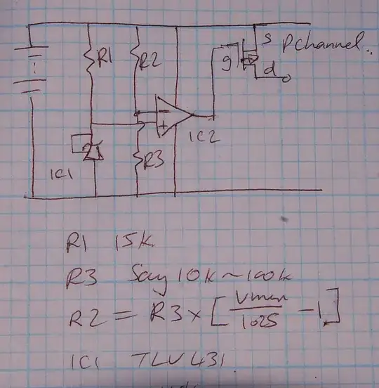
(1) Opamp based
P Channel FET high side switch.
TLV431 1.25 V reference.
R2/R3 divide Vmin to = 1.25V.
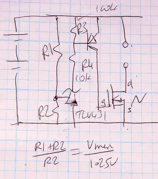
(2) N Channel FET, low side switch.
TLV431 1.25V reference.
FET Vth << Vmin
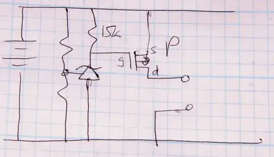
(3) P Channel FET, high side switch.
TLV431 = 1.25V reference.
FET Vth << (Vmin-1.25)V
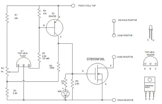
(4) From web - similar to my N Channel low side circuit.
From This discussion page.
Here R6 adds hysteresis.
Russell McMahon
- 147,325
- 18
- 210
- 386
-
Hi, If it was NPN instead of PNP, which was wired such that its collector cuts-off another N-Channel Mosfet's gate. How would you add Hysteresis to TL431. Asking because I have such a circuit..to which I need to add some hysteresis. Ideally, Hysteresis should be added from the output to the non-inverting terminal. But here the output is wired to be the base of a another transistor. If I add a hysteresis resistor from TL431 output to its reference pin, would that not configure it, in its regular closed-loop arrangement. That would not help...I think. Please correct and advise. – Vishal Apr 02 '17 at 20:33
-
@Vishal Hysteresis is the same as positive feedback. In this case, when the ref pin of the TL431 is taken above Vref_internal hysteresis is used to raise it slightly more again by "mixing" an external positive going signal with the input being sensed. In the diagram above this is achieved by adding current via R6 to make the voltage on the R2 wiper rise. SO In a different circuit, look for a point which goes positive when the TL431 input exceeds the Vref voltage and take feedback from there. ... – Russell McMahon Apr 03 '17 at 06:43
-
... Your circuit SOUNDS wrong as an NPN turning on will clamp an NPN low = off which will unclamp an NCHannel gate so FET turns on. BUT regardless, when the TL431 turns on some points will go high and some low. Choose a high one that can tolerate the small feedback load and use it to drive TL431 ref pin via a suitable resistor. – Russell McMahon Apr 03 '17 at 06:43
-
Thanks Russel. I now understand it much better...it was more intuitive earlier, but your explanation makes it much clearer. In my case, I am using the TL431 output to turn an NPN ON, which will inturn shut off an N-Channel Mosfet, because the NPN creates a short to the ground, which is seen by the Mosfet gate. So, in a sense, I only have the collector of the NPN going from high to low, as TL431-ref pin moves from "higher > 2.5V > lower". I dont have a point which goes towards positive...Should I send a pic of the circuit ? – Vishal Apr 04 '17 at 20:35
-
@Vishal Best would be to post a new question with your circuit. Your explanation is ambiguous. Does the NPN turn on when the TL431 turns on, or NPN turns off when the TL431 turns on?. | If the TL431 turns on the NPN when the TL431 turns on the cct is liable to be "strange" but the NPN base goes high when the Vref goes high so can be used for feedback. | If the NPN turns off when the TL431 turns on then the NPN collector goes high when Vref goes high so can be used for feedback. If postiong a question pse advise me of it - perhaps by a comment here. – Russell McMahon Apr 05 '17 at 11:03
-
@RussellMcMahon, I have now removed the TL431 version and used LM358 as comparator. For hysteresis, i am using a 100K resistor and it gives me about 0.6V of Hysteresis...which should be good enough. The comparator output is sent to IRFZ44N N-Channel Mosfet gate...which is used here as a low side driver. This is working fine and so it should suffice. Thanks for all the efforts. Will post a new question, if something arises in this circuit :) – Vishal Apr 05 '17 at 12:53
-
@RussellMcMahon, Before LM358 I had used TL072, which was OK, except that low side voltage swing was at 1.1V instead of 0V. Then I read that LM358 goes much closer to the negative rail..which is good because that way the mosfet gate is far away from its Vgs(th) of 2V, when turned off. Another big observation was that when the LM358 supply was directly connected to the Battery, things were not so clean; switching was erratic. Now I have used a 9V zener to stabilize the IC supply, and things are much more clean :-) – Vishal Apr 05 '17 at 12:58
-
@Vishal A problem is that you have presented glimpses of your requirement and not a full picture. It may be that what you have now will work properly - but without a better understanding there may be things we miss. You mention a low side driver, which usually (not always) implies a switching cct where speed matters. An LM358 may be too slow depending on what your applicatyion is. – Russell McMahon Apr 05 '17 at 13:04
-
@RussellMcMahon, My application is a low-battery-voltage cut off circuit for an LED emergency light...and hysteresis is used to keep it cut-off until Battery voltage rises to a significant value. – Vishal Apr 07 '17 at 09:37
6
You could use a reset IC like the MAX809. This will output a low level when the input voltage is below the device's threshold. If the input voltage is higher than the threshold the output follows the input.
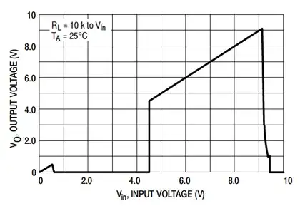
You can use this voltage to switch an N-channel MOSFET, like the FDC653N.
You'll have to use a high resistance voltage divider for the input voltage, since the highest threshold available is 4.9V.
The MAX809 has several manufacturers. I prefer the OnSemi because of its low ground current.
stevenvh
- 145,145
- 21
- 455
- 667
-
It seems that the MAX809 doesn't provide hysteresis. Is there a simple way to achieve hysteresis, to prevent the circuit from oscillating? – Danilo Bargen Jun 07 '20 at 11:41
1
I am not at all familliar with LiPo batteries.
But To detect the Voltage level going below certain limit, You can always use OP-AMPS...
I have this age old book... Hope it helps you--
Swanand
- 3,245
- 5
- 28
- 45
-
Thanks Swanand. One aspect of LiPo battery cells is that if they are discharged below 3V they lose the ability to be recharged. – Mark Harrison Sep 20 '11 at 08:11