15

I have a project that involves a specific single board computer* and several hundred WS2812B "smart" RGB LEDs*, all running from a 5V supply.

I have a 5 volt 15 amp unregulated power supply. While the LEDs are okay with an unregulated power supply the microcontroller I am using tends to have issues when the voltage is not steady.

Since I want to run it all from one power source I would like to create about 1 amp of regulated 5V power from the unregulated 15A 5V source.

I want to build this power converter onto a PCB, so I am looking for a design I can implement and not a pre-made board. My final design will be a Pi hat, that is it will clip onto the Pi's GPIO ports and sit on top.

This will all be soldered manually(through hole or surface mount) so ideally it will not involve more parts than needed. This is a one off so while cost is a concern I am not trying to save pennies.

What type of power converter circuit could I build onto my board that can do this? Converting only 1 amp will I encounter significant heat issues?

I am not asking anyone to design this for me, rather point me in the correct direction.


*The WS2812B is an 'intelligent' serial data controlled LED RGB light source integrated in a 5050 package. Connections are digital serial in and out plus 5V & ground. pins. It also include a precision internal oscillator and (internally generated ) 12V constant current drive. Devices are series chained (Dout to next Din) allowing up to 1024 devices and a 5 metre long string on a single series connection.
For more details see the data sheet here

*Raspberry Pi 2 B
HighInBC
  • 925
  • 1
  • 7
  • 26
  • 3
    I am new here so if whoever left me a down vote could explain why then that will help me do better next time. – HighInBC Oct 21 '15 at 19:26
  • 7
    They ***wrongly*** think this is a shopping question, because you are new, and mentioned Arduino/RPi. People around here hate anyone that mention those. I'm surprised it wasn't singlehandedly migrated out yet. – Passerby Oct 21 '15 at 19:32
  • 14
    I will keep that in mind and next time just call it a "small 5V computer". – HighInBC Oct 21 '15 at 19:45
  • 2
    The end use shouldn't matter. A question on how to regulate a un-regulated transformer of the same voltage is squarely on-topic. – Passerby Oct 21 '15 at 19:47
  • Don't take Passerby too seriously. This is a recurring political issue with him, so he uses any excuse to beat this dead horse even more. It's true that mentioning arduino is a bad idea, and the non-standard uses of "shield" and "sketch" pretty much guarantee you will be downvoted to oblivion. The RPi has much less of a stigma attached to it. However, I doubt this has anything to do with the downvote. I didn't downvote, but I suspect it is due to mentionin WS2812B like we're supposed to know that those are, but without giving any pertinent specs. – Olin Lathrop Oct 22 '15 at 11:18
  • Also don't take a single downvote too seriously. It really only takes a couple of popular answers for a new user to rise to the rep level where they can downvote. As for mentioning but not detailing the WS2812B I think that's perfectly appropriate given that it's part of the background, not part of the core question. – Peter Green Oct 22 '15 at 13:33
  • @HighInBC Actually, mentioning Arduino/RPi/whatever is not that bad, it helps people to tell how much power you will need, which is totally unclear if you call it a "small 5V computer". Of course you could avoid bringing up RPi altogether and say you needed a 5Vx1A regulated PSU with unregulated 5V as input. – Dmitry Grigoryev Oct 22 '15 at 13:49
  • 1
    Don't takle Olin too serious *on this issue* (but take complete notice of him on anything technical) - this is a recurring political issue with him, so he uses any excuse to beat this dead horse even more. [[ :-) ]] Don't take my comments on Olin too too seriously, except the ones on his technical ability, this is a recurring ... . -> Abend: Pending recursive loop detected. || Olin's comment re WS2812B may well be correct. Or the random downvoters may have chosen you for their daily gift, as seems to happen. – Russell McMahon Dec 17 '15 at 01:38

4 Answers4

13

What you want is reffered to as a "non-inverting buck-boost converter". There are a few different topologies of switched mode converter that can achive that.

Unfortunately all of them are more complex than a simple buck converter (only steps down) or boost converter (only steps up).

A quick google found a Ti appnote comparing the options. http://www.ti.com/lit/an/slyt584/slyt584.pdf

National semiconductor have an online tool called webbench that will design this stuff for you. Only downside i've found with it is it likes to pick parts that are a PITA to solder.

Peter Green
  • 21,158
  • 1
  • 38
  • 76
  • +1 This is good information. I have a bit of reading to do. – HighInBC Oct 21 '15 at 19:21
  • 1
    Let me inform that National Semiconductor is no more. They were bought out by TI some time ago. As a matter of fact you can now find the WebBebch design tool hosted on the www.ti.com web site. – Michael Karas Oct 21 '15 at 19:31
  • I have accepted this answer as it does seem to be pointing me in the right direction. – HighInBC Oct 21 '15 at 19:40
  • 6
    You might consider just boosting enough to then linear-regulate back to 5V. Less efficient, and might be impractical, but you should at least do the sums. –  Oct 21 '15 at 21:10
  • Not a bad idea. Efficiency is not that big of a concern as the computer does not draw very much. – HighInBC Oct 21 '15 at 21:19
  • 1
    A boost converter followed by a linear regulator is probablly of similar overall complexity to a sepic or dual-switch buck boost converter. So i'm not sure I see much point. – Peter Green Oct 22 '15 at 13:36
  • Peter - unrelated to this post - Thanks for fuse related comment - I've deleted the reference - I don't know if it was rubbish when I originally used it. – Russell McMahon Dec 17 '15 at 01:31
3

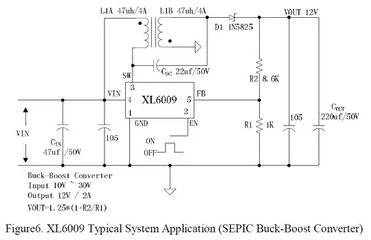
The datasheet of XL6009 converter has several reference schematics, including one for non-inverting boost-buck converter:

enter image description here

You will have to adapt it to output 5V instead of 12V by replacing R2 with a 3.0K resistor, according to the formula above. The input range depends on the output voltage and current, so your unregulated 5V source should be in range for a 5V regulated output.

Dmitry Grigoryev
  • 25,576
  • 5
  • 45
  • 106
  • 1
    The datasheet for the XL6009 says the input voltage can range from 5V-32V. If my unregulated 5V supply drops below 5V won't that be a problem? – HighInBC Oct 22 '15 at 13:57
  • 1
    Fair remark, actually. I used this chip with Li-Ion as input (between 3.7 and 4.2V) with no issues, and e.g. [this site](https://www.openimpulse.com/blog/products-page/product-category/xl6009-dc-dc-step-converter-boost-converter/) claim their [boost converter based on XL6009](https://www.openimpulse.com/blog/wp-content/uploads/wpsc/downloadables/XL6009-Schematic-Diagram.pdf) works from 3V up, but the spec doesn't guarantee it. – Dmitry Grigoryev Oct 22 '15 at 14:04
  • 1
    I will take reality over specifications any day. – HighInBC Oct 22 '15 at 14:05
  • At least the absolute maximum ratings of XL6009 don't forbid you to go below 5V. I guess you may not get the claimed efficiency or full 4A switching current though. Thanks for mentioning it, I overlooked this line of the spec. – Dmitry Grigoryev Oct 22 '15 at 14:10
  • Another solution could be adding the regulating circuitry to the unregulated supply, to provide regulated 5v 1A as well as unregulated 5v 15A. You would "tap" into the source of the unregulated 5v. – Guill Oct 22 '15 at 23:53
2

Why build one yourself when you can buy a small boost-buck converter for less than ten bucks? I have a rather positive experience with this one. It's small, low profile and is a breeze to solder (4 holes in the corners, 2 for input and 2 for output): enter image description here

FYI, the size of this thing is 44x21x13mm, so it may well fit between your custom PCB and the RPi.

Dmitry Grigoryev
  • 25,576
  • 5
  • 45
  • 106
  • 1
    As I mentioned I am building a PCB that needs to fit a form factor. I could certainly use the components and design from a board like that though. – HighInBC Oct 21 '15 at 21:38
  • 2
    Why answering that way, when it is clearly stated in the question that he is not looking for pre-made board? Even if he didn't stated it - this is not answering the questions in any way, people read stackexchange for learning, not shopping-recommendations, read http://electronics.stackexchange.com/help/on-topic Stuff like this should be in comments, not in answer(if it should be at all, because question specifically says "no" to off-the-shelf boards) – ScienceSamovar Oct 21 '15 at 23:01
  • 2
    not to mention that the converters on your link is overpriced, you can find identical(even from the same manufacturer) converters much cheaper(around $3 each) – ScienceSamovar Oct 21 '15 at 23:05
  • Why can't one stack this pre-made board on the custom PCB and be done with the converter, concentrating on the rest of the design instead of reinventing the wheel? In the end, of course, it's your choice. – Dmitry Grigoryev Oct 22 '15 at 10:59
  • 1
    @DmitryGrigoryev, because the point is to learn how to do it and apply these skills in further projects(that go to production for example, you can't use this kind of things in production). Of course you can user pre-made boards and pre-written code for everything, but that means that in the end you barely know what exactly your circuit do, you just know big modules. Anyway that's not the point, my point was if person asks you how to make some circuit and make calculation - giving him link to store and saying "don't bother, just buy" is little discouraging him from learning. – ScienceSamovar Oct 22 '15 at 14:23
-2

My 2012-2013 raspberry pi advertised as needing "5V regulated" turned out to need 4.88 to 5.02 V to boot and >4.4V to continue operating. Since your 15A main supply might momentarily go over 5.02 volts at times, I wouldn't trust it.

If you can tolerate some green LED being always-on, you could use some as an 'overflow' at 4.9 Volts with pairs of greens parallel to the rPi, which go from the threshold of minimal brightness at about 4.8V to quite brightly on at 5.2V. From your 15A supply, run a length of 2Amp rated cable to your "overflow regulator" board comprising nothing but pairs of green LED, and enough of them to dump an Amp at 5.2V, though normally they should be using a lot less. Aim is for it to settle to near to 5V on this board with the rPi off. use longer 2A supply cable (for its resistance) if necessary. Depending on what sort of unregulated 15A supply it is, you might also want a fat capacitor on the "overflow regulator" board. From 5V rms unregulated rectified (one of the worst kinds of unregulated), it needs an extra resistor between unregulated supply and the overflow board, and a supercapacitor.

Next you want enough length of 2A rated wire from this board to the "0" and "+5" lines of the pi, possibly with a switch in there, and aiming for 1/20 to 1/8 ohms in these supply leads. (most multimeters don't measure as low as that properly). Switching on the rPi should make the greens noticably dimmer and give you a steady 4.9V at the rPi.

Please post here and on an rPi forum the measured voltage between TP1 and TP2 as that is where I expect it to need 4.9Volts (which gets advertised as "5")

  • 2
    Using LEDs to regulate voltage is unprofessional to say the least. The resulting voltage will drift a lot over time as the LEDs warm up. Also, it's a waste of perfectly good LEDs. – Dmitry Grigoryev Oct 22 '15 at 13:58
  • a zener diode would be much more appropriate. – Stefan Paul Noack Oct 22 '15 at 15:12
  • 1
    @noah1989 yeah, but you'll need a lot of them to stabilize 2A, so you'd add a transistor and make a linear regulator. And then you'd take into account that your input voltage may be lower than 5V, and add a boost converter to it. In the end, you'll get to boost-buck converter eventually (not you personally, just someone trying to follow this approach). – Dmitry Grigoryev Oct 22 '15 at 15:26