4

I'm trying to understand the schematic of the Apple 1 computer power supply.

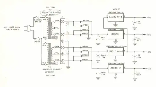
Nothing surprising at first sight. Two power transformers (117 VAC -> 10 VAC / 117 VAC -> 28 VAC), two diode bridges, and four voltage regulators (+5V / -5V / +12V / -12V).

enter image description here

But looking closely, I can't understand the logic here.

While the +5 volts output uses the first power transformer, through rectification and regulation, the -5 volts output uses the regulated -12 volts output.

So basically, why is that? Why doesn't it use the rectified output of the 10 VAC transformer, as does the -12 volts output with the second transformer?

Or maybe why is there two power transformers? If the -5 volts uses the regulated -12 volts, why can't the +5 volts use the regulated +12 volts?

And if I may ask another question here, what about the capacitor values? Looking at the datasheets for the voltage regulators, capacitor values look really huge.

For instance, typical application schematic of the LM323 uses 1uf and 0.1uf capacitors. So what's the benefit of using such high capacitance in the Apple 1 power supply?
Macmade
  • 281
  • 6
  • 16

3 Answers3

7

Why not take the +5V from +12V?... To begin with... look at the diodes. MR500 is rated for much more than N4001 in terms of current [3A vs 1A, if I recall correctly]. Also note the larger 5300uF cap on the 5V rail. Both indicate a higher current is needed from this rail. Also note that despite similar names, the LM323 and LM320 have different current ratings. 3A for the former but only 1.5A for the latter. Furthermore, as Passerby notes, the Stancor P-8667 is rated for 1A output while the P-8380 is rated for 3A.

The -5V rail probably needs less current as Peter Bennett says because of the internal construction of the Apple-1 computer, which isn't shown here. After looking a bit through the Wikipedia pages, the Apple-1 CPU (a 6502) was not actually TTL-based (as you might infer from Peter's answer), but was made in the first generation depletion-load NMOS, which indeed needed only one power supply, thus the emphasis on the 5V rail. You can see in this low-quality schematic that the Apple-1 CPU indeed used only the 5V rail. The 6820 PIA used that +5V and the +/-12V rails as well according to what I can see there. The -5V rail was used by the RAM. Apparently this was Mostek 4K dynamic RAM, which needed +12V (VDD) and +/-5 V (VCC/VBB) supplies.

The 2400uF caps are the filter for the bridge rectifier. The input caps for the LM320 are omitted altogether because of the close proximity of the rectifier caps. The filter caps are normal in size for linear psu of this kind (high output current). You can look at Full-wave bridge rectifier with capacitor filter and ripple voltage for calculation details. To be more accurate, the +/-12 supply is split/dual rail bridge rectifier, like you usually see in audio applications. The +5V one is classic bridge rectifier.

And finally regarding the output caps (after the regulators): the datasheet shows minimal values to guarantee operation. Larger caps generally don't hurt [stability] with these old (high-dropout) regulators, but ensure a better transient response with fast variations in load, which is not uncommon for digital circuits. A much more recent ATX supply (which I've seen use LM7912 and LM7905 for the low power negative rails) also has fairly high output caps; one or two hundred uF are easily seen these days after a linear reg (because of the advanced in electrolytics that make them cheap enough) and if you look at the datasheet recommendation... it's nowhere near that.

Fizz
  • 14,355
  • 2
  • 43
  • 97
  • 1
    Thanks a lot for your awesome answer. Very hard to decide between accepting yours or the one from @Passerby. I decided to accept his because of the note about wasted Watts from the regulators, but your answer is very appreciated. : ) – Macmade Oct 28 '15 at 19:30
5

The odd (to us, natch) setup is due to the use of standard parts, and linear regulators.

Assuming the STANCOR P-8667 (28V, 1A) and P-8380 (10V, 3A) were standard off the shelf (read: cheap and easily available) transformers, since Steve and Steve were building this, from scratch, in their garage, having sold their car for funding, and expecting to sell it as a partial kit. The customer would have to provide the transformers.

Then we figure out the best arrangement to maximize efficiency while minimizing heat. They only had linear regulators at the time, not very efficient, high drop out voltage, physically big. Not like today's high efficiency tiny switching regulators with millivolt drop outs. The LM323 for the +5V rail is a 3 Amp regulator. Assuming all 3 Amps were needed, that means 30 Watts through that lone Transformer, half of which is wasted on the Regulator. 15 Watts of heat right there. Same for the 12V reg, at 1 Amp, that's 28 Watts through the regulator, 16 Watts wasted.

Had they connected the 5V regulator through the 12V regulator, they would 1, need a much beefier 12V regulator, as well as a much beefier transformer. Combined they would need to carry at least 28V * 4A = 112 Watts, for the combined +12V (1 Amp) and +5V (3 Amp) draw. 64 Watts of which would be wasted on the +12V regulator as heat, and another 21 Watts wasted on the 5V regulator.

Comparing the two numbers, we get a waste of 31 Watts in the chosen design, and 85 Watts in the Single Transformer, Series Regulator design. Did not account for any loses from the rectifier or transformers, minor in comparison.

Consider the cost of electricity, heat management, and the planned need for customers to source their own transformers, which two smaller ones would likely be easier to find than one beefy one, the design is the smart choice.

If you read anything about the construction of the Apple I, keep in mind, that it revolved around two cash strapped guys working out of a garage. Cost was always a concern. The thing didn't even use ram for the display, they used shift registers cause it was cheaper.

Passerby
  • 72,580
  • 7
  • 90
  • 202
  • The Apple II switched to a much more efficient switching power supply, naturally, as started to be common at the time. – Passerby Oct 20 '15 at 22:40
  • 1
    Thank you very much for the detailed answer. Awesome notes about the wasted Watts, which made me understand a few more things : ) – Macmade Oct 28 '15 at 19:28
2

The current provided by the +5V supply will be much greater than that provided by the other supplies. (think bipolar TTL chips here)

There will be very little current required from the -5v supply, so it can be easily derived from the -12V supply.

The capacitors between the rectifiers and the regulators are for bulk storage. The 1 uF and 0.1 uF capacitors we normally see recommended on the regulator inputs and outputs assume you are starting with a fairly steady unregulated voltage - the bulk storage capacitors are assumed to be some distance away from the regulators.

Peter Bennett
  • 57,014
  • 1
  • 48
  • 127