7

I'm trying to measure the capacitance of a very low capacitance sensor (two parallel plates across a block of foam). This is a self-produced force sensor; I'm trying to eventually use some of the work presented here. I'm estimating that the capacitance should be in the neighborhood of 90 pF.

I started with the CapacitanceMeter tutorial from the Arduino web site. I modified it to use micros() instead of millis() and output pF instead of nF. I also swapped in a 10 megohm resistor in place of the 10K ohm one, and updated the code. However, I'm getting readings that swing by over 50 pF.

How can I improve the accuracy of the setup?

Thanks!

FarO
  • 1,306
  • 1
  • 13
  • 33
David Pfeffer
  • 215
  • 1
  • 3
  • 8
  • 1
    The RC time constant method is actually capable of measuring single picofarad changes, however you need a circuit without leakage paths such as a dirty PCB. More important, you can't have your hands anywhere near it as they introduce variation larger than what you are trying to measure. If you want to measure plate proximity and not hand proximity you will probably need a fully conductive user facing surface as a shield. – Chris Stratton Feb 23 '16 at 16:10
  • 1
    With the right pin selections you can use the analog comparator and hardware timer, though if I recall you may have to have software in the process of starting each charge measurement cycle, so be sure to disable interrupts during that critical sequence. – Chris Stratton Feb 23 '16 at 16:18
  • 1
    Possible duplicate of [Using an Arduino to measure wire capacitance](https://electronics.stackexchange.com/questions/204305/using-an-arduino-to-measure-wire-capacitance) – Dmitry Grigoryev Sep 17 '18 at 07:06

3 Answers3

8

You can get an approximate measure of the capacitance with just 2 microcontroller pins, 1 resistor and 1 known capacitor. The circuit looks something like this:

cap sensing circuit

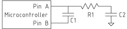
C2 is the unknown capacitance you're trying to measure. C1 is a reference capacitor of known value, and about 50-1000 times the value of C2. R1 isn't too critical, 1k Ohm or so.

The idea is to charge C2 with a known voltage (5 or 3.3 V, whatever V+ is), and then transfer its charge (q = C*V) into C1. Each time we transfer the charge from C2 to C1, C1's voltage increases by a tiny amount proportional to C2. The number of times we have to transfer charge to make C1's voltage exceed some threshold (for us, the logical "1" threshold of pin A) is then inversely proportional to the value of C2.

The trick is to take advantage of the high-impedance state of the microcontroller pins. If we kept the bottom side of C1 grounded while charging C2, then we would also end up fully charging C1. Instead, we let the bottom side of C1 float by configuring pin B as high-impedance. Now, whatever the top side of C1 does, the bottom side does too, always keeping the same voltage across C1.

The measurement algorithm goes like this (in pseudo-C):

// Step 0: discharge C1 to prepare for a new measurement
PIN_A = 0;
PIN_B = 0;
delay(some_time); // long enough to discharge C1

bool under_threshold = true; // has the voltage across C1 exceeded the threshold?
int count = 0;
while (under_threshold)
{
    // Step 1: Charge C2
    PIN_B = Z; // Z means high-impedance
    PIN_A = 1;
    delay(some_time); // long enough to charge C2

    // Step 2: Transfer charge from C2 to C1
    PIN_A = Z;
    PIN_B = 0;
    delay(some_time); // long enough for C2 to discharge into C1

    // Step 3: Check if the threshold is exceeded
    if (PIN_A || (count > COUNT_MAX))
    {
        under_threshold = false;
    }
}
return count;

You can see a demonstration of the circuit at https://www.circuitlab.com/circuit/uq2zs6/cap-sensing/

Theran
  • 3,432
  • 1
  • 19
  • 21
5

Small capacitances are best measured using an HF oscillator, and measuring the change in frequency with and without the DUT in the oscillator tank circuit. The capacitance can then be calculated. This could be done automatically on the Arduino, and the result displayed. Here is the schematic for a PCB I designed for the Elsie LC meter which uses that technique.

Using conductive foam and measuring the change in resistance as it is compressed would be easier.

Leon Heller
  • 38,774
  • 2
  • 60
  • 96
  • The goal here is to measure changes in compression at various locations in the foam, by silkscreening electrodes onto the nonconductive foam at regular intervals to make a "pixel" pattern. – David Pfeffer Sep 18 '11 at 13:29
  • How would one take the capacitor into/out of the tank circuit using something other than a relay? – David Pfeffer Sep 18 '11 at 13:35
  • I'm rather confused honestly on how to produce a simple HF oscillator... measuring it seems straightforward but not producing it. Ideally it would seem that I somehow use my variable "foam" capacitor as a tuning capacitor for the circuit? – David Pfeffer Sep 18 '11 at 13:59
  • I've added the schematic for my version of the Elsie LC meter. – Leon Heller Sep 18 '11 at 13:59
  • Would there be a way to accomplish this without such complex circuitry? I'm looking at potentially reading 30+ of these capacitors, and this looks cost prohibitive. – David Pfeffer Sep 18 '11 at 14:18
  • (I'm referring to the fixed capacitors, inductor, and op-amp, not the microcontroller and related circuitry which of course is provided by the Arduino in this case.) – David Pfeffer Sep 18 '11 at 14:19
  • You need to rethink the whole approach. – Leon Heller Sep 18 '11 at 15:02
  • I'm just really confused. I remember back in high school doing a parallel plates capacitor lab where we were able to experimentally verify a capacitor's capacitance using the RC constant and charging time. – David Pfeffer Sep 18 '11 at 15:47
  • @DavidPeffer: Scan by row and column, as it says to do in the PDF you linked to. You can switch things in and out of the sensing circuit using FETs. This is similar to the way DRAM works. http://en.wikipedia.org/wiki/Dynamic_random-access_memory#Operation_principle – endolith Sep 19 '11 at 00:02
0

Since you use a capacitive force sensor and you want to know the real time value of the capacitance, you can use a sauty bridge.

schematic

simulate this circuit – Schematic created using CircuitLab

With Cx : the capacitance you want to measure. C, R and E are known.

By applying Kirschof's laws, you have :

$$Vm=E.\frac{C-Cx}{2(C+Cx)}$$ By measuring Vm you can have Cx :

$$Cx=C.\frac{E-2Vm}{E+2Vm}$$

The resolution depends on the constants you are using and the quality of the Voltmeter you use.

  • If E is a DC voltage soucre as displayed, you can't measure anything reasonable with this circuit. – Curd Feb 23 '16 at 13:06
  • Woops, I used the wrong sign. – Raphael CREPINGE Feb 23 '16 at 15:29
  • Done, it's modified. It is a sine voltage source – Raphael CREPINGE Feb 23 '16 at 15:35
  • This can be a good method in some settings however measuring the amplitude of a fast sine wave in an embedded system may not be trivial. Measuring instead the RC time constant to charge to the ATmega's built in comparator can be simpler, and in the case of the expected short time constant many measurements can be averaged, not unlike your running oscillator. The actual error observed may well be genuine variation such as from hand proximity. – Chris Stratton Feb 23 '16 at 16:16
  • 1
    This answer totally misses the "Arduino" aspect of the question. I don't think it's obvious how to implement a sine source and an AC voltmeter using Arduino hardware. – Dmitry Grigoryev Sep 17 '18 at 07:09