17

So I've found a motor circuit which looks like this:

Motor

Since many users here believe that my hand-drawn circuit schematics are in fact pictures of flying spaghetti monster, I'll also provide a written description:

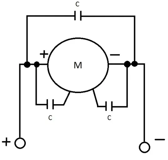
There are two input lines marked + and - going to the motor. There is a capacitor connected in parallel with the motor. There is one capacitor connected to the positive side of the motor and the motor's metallic body and there is one capacitor connected to the negative side of the motor and the motor's metallic body. The capacitors look like multilayer ceramic capacitors and have capacitance of \$0.1 \mbox{ } \mu F\$. The motor is a Kysan Electronics FK-180SH-3240 DC motor. It is also worth noting that the motors have nominal voltage of 3 V, but are powered by a 2 cell LiPo battery and are controlled by a microcontroller-based circuit.

So my question is: Why use 3 capacitors, with two being connected to the motor body? It would seem logical to have capacitors on motor terminals to keep interference away from the microcontroller, but I don't see how having capacitors soldered to the motor body would help.

AndrejaKo
  • 23,261
  • 25
  • 110
  • 186
  • 9
    It's good to see a fellow Pastafarian in our midsts... – Majenko Sep 15 '11 at 11:25
  • 1
    I came across something identical to your post while I was repairing one of my Remote Controlled cars. According to what I found out on the internet is that the main purpose of the capacitors is to reduce noise produced by the DC motor, that can affect nearby appliances. There are 3 ways of connecting the capacitors. Here is a link of the detailed methods: http://www.beam-wiki.org/wiki/Reducing_Motor_Noise –  Oct 23 '14 at 17:44

2 Answers2

13

This is just a guess, but they probably help reduce RF emissions. If you have a spectrum analyser, you could run the motor with and without the extra two caps and see what difference it makes. Perhaps something as simple as a AM radio nearby tuned between stations can give you a qualitative difference.

Olin Lathrop
  • 310,974
  • 36
  • 428
  • 915
  • Well the device is remotely controlled and from what I've heard in the era before the use of such capacitors, glitching was common. I still don't see how putting more capacitors between motor connectors wouldn't work here. – AndrejaKo Sep 15 '11 at 11:12
  • My guess was that the body was typically left floating and acted as an antenna or reflector for RF emissions. Placing the capacitors like that may have helped to isolate some noise. – Kellenjb Sep 15 '11 at 14:28
  • I think Olin and Kellenjb are right, it looks like they are for EMI purposes with pure DC drive. If the motor is driven with PWM though I think it might make things worse, as it will inject energy into the chassis. – Oli Glaser Sep 15 '11 at 17:46
  • 3
    They are definitely for EMI purposes. I used to be into RC cars, and several of the speed-controller manuals I had explicitly stated such. – Connor Wolf Sep 15 '11 at 22:34
8

How's this for a theory? Shoot it down in flames if you like...

The spinning magnetic field inside the motor (be it a spinning electromagnet in a brushed motor or a spinning solid-state magnet in a BLDCM) induces an alternating electric field into the metal body of the motor. The average potential of this field is zero, but the instantaneous potential could be quite high. The capacitors are there to leech this electric field away from the body before it can radiate out from the body, thus reducing the possibility of it interfering electromagnetically with the surrounding delicate electronics.

Majenko
  • 55,955
  • 9
  • 105
  • 187
  • 1
    When I asked this question, I was looking for answers which are more like this one, that is to say which explain what is happening. So any reason for the downvote? I'd rather not accept a wrong answer. – AndrejaKo Sep 16 '11 at 12:45