I want to build a camera obscura as an art project that produces photos of WiFi signals. The idea for now is to build a 125cm x 125cm x 125cm Faraday cage (using fine copper mesh) with a centered hole (diameter of 12.5cm) and 20 x 20 disc shaped copper plates as sensors at the back. Would this work at all? Would diffraction at the hole completely destroy the picture? Are there any conceivable alternative approaches? Thanks.
-
1Even assuming the implementation is perfect, do some simulation to be sure you will actually get something. You don't want to spend a week or more, not mentioning the money, to find out you get blurred stuff with no details. For example, with visible light a smartphone photo (iPhone 6) is about 2400x1800 times the diffraction spot (4.8x3.6mm, 2 micron diffr. spot). In your case you may get a 20x20 pixel image... you won't see much, you need STRIKING details in the source waves to detect anything meaningful in the final image. – FarO Oct 07 '15 at 08:37
-
6Also a similar question here: http://photo.stackexchange.com/q/69587 – Eugene Ryabtsev Oct 07 '15 at 11:34
-
Remember that a radar system is essentially a radio camera with a flash attached. The systems cost a lot and are the size of a large truck up to an office building. If you do build something cool make sure to let us know! – Phil Oct 07 '15 at 16:35
-
@OlafM Do you or someone else happen to know a EM radiation simulator that solves the Helmholtz equation for 3D scenes with differently reflecting and absorbing materials? – Lenar Hoyt Oct 07 '15 at 19:55
5 Answers
Well, it has the potential to work. You would have to line the inside with RF absorbing material, otherwise the incoming waves would just bounce all over the place.
Using copper plates to detect the RF power probably isn't the best idea. I would recommend using actual wifi antennas for that purpose, each one connected to an LNA and 2.4 GHz bandpass filter and crystal or diode detector.
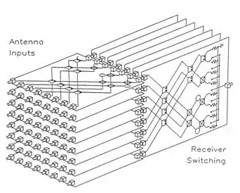
Another (probably better) option to consider would be a phased array setup. This is a bit more complicated, but you would not need the box or RF absorbing foam. In this case, you would take an array of antennas (say, a 4x4, 8x8, or 16x16 grid) and connect them to a set of devices called Butler matrices. A butler matrix is a type of passive beam forming network. These devices consist of hybrid couplers and phase shifters arranged in such a way that they map distinct 'beams' out of the array to separate ports. Basically, the idea is they act like a lens, except the focusing is done AFTER the signal gets captured by the antennas. For a 4x4 grid of antennas, each butler matrix requires 4 hybrid couplers, and you would need 8 matrices - 4 for horizontal and 4 for vertical. You're fortunate to be working at 2.4 GHz - it's possible to build reasonably-sized hybrid couplers at that frequency just in copper on a circuit board, making it possible to build a complete butler matrix on a single PC board, with no components aside from the connectors. It would be possible to build 8 port or 16 port butler matricies (had to be a power of 2), though the larger the matrix, the more complicated it gets. The outputs of these would then get passed through LNAs, 2.4 GHz bandpass filters, and crystal or diode detectors.
Picture of butler array interconnection for an 8x8 antenna array:
- 40,694
- 1
- 68
- 109
-
3Phased arrays are really the only practical way to go. Check out RF radars - almost all of those share this principle. – Dmitry Grigoryev Oct 07 '15 at 06:38
-
1Certainly. Phased array radars are actually a bit old now, most of the current systems are actually AESA arrays. AESA = active electronically scanned array. Basically a phased array, but each element has its own TX and RX amplifier and the phase shifting is done in DSP with very powerful FFT engines. However, the overall principle is the same and I think butler matricies built on standard FR4 is going to be the most straightforward solution. – alex.forencich Oct 07 '15 at 06:48
-
Thanks. I have two more question about the first idea: Could the RF absorbing foam replace the copper mesh cage? And how bad would the diffraction effects be at the hole? – Lenar Hoyt Oct 07 '15 at 08:14
-
And questions about the Butler matrices idea: That reminds me of the 'inverse' of beam forming, is that related? What would the directionality properties be of such a receiver, how much would noise from the side interfere? – Lenar Hoyt Oct 07 '15 at 08:21
-
1I would suggest using both. The mesh will block external signals, and the foam will prevent internal reflections. Not sure about diffraction, though. And butler matrices are a method of doing beam forming passively for multiple receivers. – alex.forencich Oct 07 '15 at 16:07
You might have some luck with this approach that Greg Charvat demonstrates using an LED radio detector and long-exposure photography.
The obscura idea is interesting, but getting RF to behave that way sounds... a little crazy ha! It would be awesome if you could account for and control all of the re-radiation and reflection that would probably happen.
If you can get it to work though, you'll definitely make the rounds on the hacking blogs!
- 6,168
- 21
- 33
Unfortunately you're going to run up against a limit in terms of diffraction. We know that (at least for optical pinholes), the ideal focal length for a given pinhole radius s is s^2/λ, and the spot size at this distance is about 0.6 s
From these, we can determine that for a given resolution n with a 'normal' field-of-view (think of n as the width or height of the image in pixels), the required focal length is about 0.5 n^2 λ, and the pinhole size will be 1.3 n λ.
For 2.4 GHz, the wavelength is around 12.5 cm. Thus if you want even a measly 16 × 16 image, you need a camera with a focal length of 16 meters, or 52 feet!
Ultimately you'll probably end up using the fact that, unlike with light, we can easily read the phase of incoming radio waves. But at that point you're designing an antenna, not a camera!
- 592
- 3
- 16
Diffraction through a small, wavelength-sized hole will just fill the area behind it. Pinhole lenses for light have the same problem. Your idea would work if you scaled it up, say you used a football stadium with a metal roof, made a 10 x 10 m hole in the roof, and placed sensors on the field. Not practical.
Why not consider a single pixel camera? use a wifi dish antenna, mechanically scanned across the environment, with a wifi card recording the signal strength every few degrees of movement. You could plot this on top of a panoramic photo of the scene, a bit like the way radio and optical astronomical images are overlaid.
A two foot dish has a beamwidth of about 12 degrees at 2.4 GHz, so it won't be a very sharp image, but that's the fundamental limit of the physics, which applies to any other simple camera design.
- 7,617
- 3
- 19
- 35
I just wanted to post and mention that the suggestion made by @tomnexus is quite workable.
I just finished the first tests of a similar rig. My setup uses a satellite dish with LNB, a satellite finder (to pickup the signal strength,) an Arduino, and a little software on a PC.
The Arduino controls a couple of servos and reads the signal strength from the satfinder. The PC tells the Arduino where to aim the dish, then assembles the individual readings into a bitmap.
This is view of the sky facing south from my house:

You can see three satellites in that picture. The gain was up way too high, so there aren't any details. In a normal photo you'd call that "over exposed." Notice that the gain was up high enough that there's a bit of a reflection off of something visible in the lower right corner.
This is a view half in and half out of my garage.

It is hard to match what you see in the picture to what the scanner sees. The part to the right doesn't resemble the optical view at all. There's a row of trash cans in front of a fence there, but the sat scan view just looks strange. I think that the vertical lines on the left side are the edges of the wall and that the really clear black vertical line is from a gap in the fence.
I will be posting back in a few days with some questions of my own on how to improve the sat finder part. I've just tapped into the voltage that normally drives the meter. It works (obviously) but it has some kind of threshold which makes the darker areas just turn black. I'll have to trace the circuit first, though.
It ought to be possible to build something like that for 2.4GHz using a directional antenna (maybe a pringles can antenna?) with a couple of servos and a simple diode detector with amplifier for the signal strength.
It might even be possible to detect the 2.4GHz using the satellite detector setup. If the whole thing has enough gain and you are close enough, then it might pick up enough of the out of band signal to detect and measure. I will be giving that a try as well - I've got WLAN here, so that might be worth looking at.
The SF-95 satellite detector that I'm using as a signal strength detector is rated for 0.95GHz to 2.4GHz, so it should be possible to connect a WiFi cantenna directly to it.
- 67,678
- 8
- 104
- 179
-
Nice work! Please post side-by-side optical camera photos! A sat finder might only be sensitive to the beacon frequency, while the thermal noise power covers the whole band ~0-1 GHz. Your system might benefit from a wider bandwidth detector, even just a small amplifier and an RF diode would cover 100 MHz. You should then be able to calibrate your picture in degrees C or F. – tomnexus Jan 11 '16 at 06:11
-
Also, aim for a scene at least 2 D²/lambda away, say > 30 m, otherwise you'll be in the pattern near field, or in optical terms, the dish will be out of focus. – tomnexus Jan 11 '16 at 06:27

