6

Came across an Adafruit interview with the one and only Paul Horowitz and he said something interesting. Part of interview thats related to this question

He said in more or less words that the capacitance of a line disappears when the cable is terminated.

Why does adding resistance "removes" capacitance ? If this is not what is implied in the video, then an interpretation of what he meant and small explanation would work. The focus of this question is about the capacitance.

And it's not that the resistance dominates, so capacitance is negligible, he says its actually gone. Magic.

Can someone call Howard Johnson about this ? Paul Horowitz is dabbin in black magic.

efox29
  • 11,827
  • 9
  • 56
  • 102
  • Well, when properly terminated the transmission line looks like a resistor of the characteristic impedance to signals of any frequency; without termination it's reactive; perhaps that's what he meant? – Nick Johnson Oct 06 '15 at 08:55
  • 1
    Of course the capacitance is still there physically. But in a terminated transmission line the series inductance and parallel capacitance of the line to the shield can cancel each other out. So within a certain frequency range and when terminated properly (to counteract reflections) a transmission line can behave like it has no capacitance. – Bimpelrekkie Oct 06 '15 at 09:11
  • 1
    So is this a real question? He actually gives the scientific explanation 3 seconds after his "magic" remark. If you somehow missed that: http://electronics.stackexchange.com/a/75372/54580 – Fizz Oct 06 '15 at 09:13
  • @RespawnedFluff yes its a real question and no he doesnt go into a scientific explanation. The proposed link to the question does not address my question of why does the capacitance disappear. The link only explains what Zo is. It does not explain why terminating the line removes/negates/cancels/eliminates/masks/vanishes/disappears capacitance. – efox29 Oct 06 '15 at 10:09
  • @FakeMoustache that makes sense. – efox29 Oct 06 '15 at 10:15
  • @efox29: Fair enough! It seems we don't [yet] have an explanation for that on-site. Alas I chickened out typing a bunch of equations (the actual *why*), but I hope the answer I wrote at least explains what H was talking about. – Fizz Oct 06 '15 at 11:34
  • 1
    In the interview, when pressed on the 'magic' remark, he says that the inductance combines with the capacitance. So capacitance does not disappear. – Chu Oct 06 '15 at 12:03
  • @RespawnedFluff ya it helps! Appreciated! – efox29 Oct 06 '15 at 12:19

3 Answers3

9

It depends what you mean by 'capacitance'. If you mean two conductors separated by dielectric, then of course it doesn't.

However, if you mean 'behaves like capacitor', then yes it does.

a) If you take (for instance) a high value resistor from a power supply, and connect it to a capacitor, then the voltage will start at 0v and slowly ramp up.

b) If you take the same resistor and supply, and connect it to a 50 ohm resistor, the voltage will jump up as soon as connected to some value determined by the resistor ratio, and stay there.

c) If you take the same resistor and supply, and connect it to any length of 50 ohm line terminated with a 50 ohm resistor, it will behave just like (b).

d) This is where it gets interesting. If you take the same resistor and supply, and connect it to an open circuited length of 50 ohm transmission line, then it will behave like (b), at first. The voltage goes up to a 50ohm value, and stays there. It stays there for as long as the voltage wave travels along the line, and still stays there while the reflection wave travels back. When the reflection wave gets back to the resistor end, the voltages add and further reflections take place. As the reflections travel to and fro, the 'capacitive' behaviour emerges. This is where you need to find a video tutorial on transmission lines.

So why is that different from (c)? When the travelling wave hit the terminating resistor, it was not reflected. Everything stopped changing, with a DC current flowing through the high value resistor, along the line, and through the terminating resistor.

e) What happens if the line is short circuited at the end? As for (d), except as the reflections build up, 'inductive' behaviour emerges.

So you can see that the 'normal' behaviour of a transmission line is resistive. It's only after the time it takes for the speed of light to make several trips along the line that the capacitive or inductive behaviour emerges. As the time for this behaviour to build up depends on the length of the line, so does the effective capacitance or inductance also depend on the length of the line.
Neil_UK
  • 158,152
  • 3
  • 173
  • 387
  • Makes sense. Good break down of scenarios. – efox29 Oct 06 '15 at 10:22
  • 1
    Good answer. Z0 of a line is also called **Surge Impedance** - the impedance seen by a surge. (at first) – tomnexus Oct 06 '15 at 11:01
  • @RespawnedFluff, for those of us looking for understanding, it would help if you eliminated the snarkiness and told us exactly what was missing. Calling it "wonderful" and then criticizing it is just passive aggressive... now I have to go watch videos of cuddly kittens to try and remove the stink of your subtle attack from my mind. – Mike S Oct 13 '15 at 14:33
7

Yes, a line becomes resistive when properly terminated provided the operating frequency is above ~1 MHz and below a few GHz.

In truth it is the inductance and capacitance that together look like a near-perfect, real ohmic resistor when the line is terminated. It's fairly simple to prove from the equation of characteristic impedance for a line. For any line (coax, parallel wires, twisted pair etc.) the characteristic impedance (Z0) is: -

Z0 = \$\sqrt{\dfrac{R + j\omega L}{G + j\omega C}}\$

Where R, L, C and G are the "per metre" values of series resistance, series inductance, shunt capacitance and shunt conductance.

At high enough frequency R and G become small compared to jwl and jwC so the equation simplifies to

Z0 = \$\sqrt{\dfrac{L}{C}}\$

You see that there is no frequency term and this makes the units of Z0 pure resistance. Remember that this only works when a line is properly terminated.

EDITED SECTION - Consider an infinitely long piece of 50 ohm coax - there can be no reflection coming back from the far end (whether it is terminated correctly or not) and this means that for all time, the end of the coax that you can test will look like a 50 ohm resistor.

Andy aka
  • 434,556
  • 28
  • 351
  • 777
  • This alas doesn't answer the question as posed here. As efox29 said in [this comment](http://electronics.stackexchange.com/questions/193747/why-does-the-capacitance-on-a-line-disappear-when-properly-terminated/193754#comment402168_193747) he already knows what Z0 is. – Fizz Oct 06 '15 at 11:30
  • 2
    @RespawnedFluff I disagree with your conclusion about my answer and your apparent down vote. – Andy aka Oct 06 '15 at 11:37
3

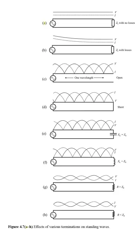
The [distributed] capacitance is said to disappear in the sense that there are no standing waves when a transmission line is terminated in a resistor that equals the characteristic impedance of the line. In that case, V and I along the line look like in the 1st (or 2nd) graph[s] below, i.e. they are always in phase. The difference between these first two is whether the line has any resistive losses. This is the "magic" that Horowitz is talking about, i.e. V and I along the line look as if the line is purely resistive when properly terminated.

You can see that in the subsequent graphs V and I along the line are never always in phase (i.e. there's a capacitive/inductive effect), even if the line is terminated with a resistor, but of a different value than the line's characteristic impedance. Furthermore, in all graphs but the first two, there are minimima and maxima along the line. It's these minima and maxima that Horowitz was talking about (in the case of an open-ended cable) prior to his "magic" remark. More precisely he was talking about how varying the generator's signal frequency results in different amplitudes measured at the far end of the cable, which is not hard to see from the 3rd graph below could happen. Then he talks about how adding a matching terminator makes the signal snap back from [a] zero as if magic happens.

enter image description here

The calculations proving this happens (actual "why") are a bit involved. I suggest you consult a[ny] textbook dealing with transmission lines, including the one from which I borrowed this image. Actually Wikipedia has the derivations too, but it's not the most mathematically clear presentation I saw (and its illustrations in this case are rather lackluster).

Fizz
  • 14,355
  • 2
  • 43
  • 97
  • Of the free material I could find on the web http://www3.eng.cam.ac.uk/DesignOffice/mdp/electric_web/AC/AC_14.html probably has most detailed (but mostly math-free) explanations. About 3/4 of that very long web page is basically "proof by example" of the issues illustrated in the graph above. – Fizz Oct 06 '15 at 12:00
  • And if you want rigorous proofs, http://www.ee.ic.ac.uk/hp/staff/dmb/courses/ccts1/01800_LinesB.pdf looks okay and it contains most of the prerequisites needed to understand the material (including an intro to phasors), but it's a 70-slide presentation. – Fizz Oct 06 '15 at 12:04
  • To see a replica of the experiment that Horowitz was talking about, look at https://youtu.be/g_jxh0Qe_FY?t=857 The only difference is that "w2aew" does things in reverse order, first shows properly terminated, then removes the terminator and shows the effect of standing waves on the signal (and he taps somewhere in the middle of the line not at the end). – Fizz Oct 06 '15 at 12:26
  • Finally, here's another presentation containing the calculations; this one's more complete than the previous one because it also includes the attenuated case (not just AC via phasors): http://122.physics.ucdavis.edu/sites/default/files/files/Electronics/TransmissionLinesPart_II.pdf – Fizz Oct 06 '15 at 12:56
  • And as a footnote, EE presentations like the above don't [usually] explain how they've solved telegrapher's equation (in the general case), but spoon-feed you the result, which is needed in the subsequent analysis (calculating the reflection factor,etc.) To see how telegrapher's equation (a PDE) is actually solved, you need to look a math text like http://www.math.umbc.edu/~jbell/pde_notes/07_Telegrapher%20Equation.pdf – Fizz Oct 06 '15 at 13:21
  • @efox29: probably the most intuitive demonstration is the mechanical analogy in http://techchannel.att.com/play-video.cfm/2011/3/7/AT&T-Archives-Similarities-of-Wave-Behavior – Fizz Nov 01 '15 at 02:11