4

UPDATE: Thank you all for your input! Looks like I'll be tapping the speaker outputs instead. Please see the new question.

Although I have lurked these forums for a while, and even though I tried to research this question beforehand, this is still my first question. Please excuse any faux-pas...es. (Fauxes-pas?) Anyway:

I have a musician friend who plays keyboard, and for his birthday, we bought him a kid's DJ toy as a joke. It's a very cheap plastic toy with some low-quality samples and a small keyboard. He would like to use it in performances, but there are no line/headphone outputs, only a small speaker (2.5 3 W, 8 Ohm if I recall correctly, I can get the exact specs if necessary). Shoving a microphone against this speaker, although certainly a workable last-ditch solution, is something he would like to avoid.

I pulled it apart, but to no avail: the speaker wires are connected to the outputs of a TDA amp chip (TDA2030 if I recall correctly TDA2822L, see image below), the rest of the PCB is featureless. Even if I could identify where to tap into the circuit for a suitable signal, the quality of the PCB and the components makes me doubt it would survive de-soldering.

Instead, I'm wondering if it's feasible to generate a signal from the oscillating magnetic field of the speaker (similar to how an instrument pickup works). I imagine it would consist, at minimum, of a coil in close proximity to the speaker and an external load. I'm by no means an expert in analog circuit design though, so I don't know if this is even possible.

Some additional info:

  • I can design PCBs and I have an affordable fabrication option, so solutions requiring PCB mounting are welcome (through-hole only, please).

  • If possible, please avoid suggesting specialty components, as these might not be available at my location (Hungary), or it might be prohibitively expensive to ship them.

  • Ideally, the output signal would be similar to that generated from an electric guitar. Barring that, line level signal would also work.

  • I would like the circuit to feature some sort of volume control, and possibly a tone knob (again, similar to an electric guitar).

  • Distortion, uneven frequency response, etc. are not a problem. Knowing my friend, I imagine the less "sterile" the sound, the happier he will be with it.

I can provide further specs or pictures if necessary. Any help is greatly appreaciated!


Update:

The original post contained a typo (25 W speaker instead of 2.5 W). Not that it matters, because I misremembered anyway, it is 3 W.

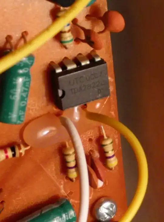
Also, based on the initial answers, it seems I have given up on the PCB too soon! The amp chip is a TDA2822L (see full markings in image below). If the datasheet is to be believed, Output 1 (pin 1) is connected to the speaker's "-" input, while Output 2 (pin 3) is connected to the speaker's "+" input. As requested, I am including images of the PCB:

PCB back side, with TDA chip near the top left corner. The white wire runs to the speaker's "-" input, the yellow wire runs to the speaker's "+" input.

back side of the PCB

Closeup of the TDA chip. As far as I can tell, the marking is:

UTC 0CC7
TDA2822L
      01

I don't have my multimeter handy right now, so I can only go by the markings here. The two resistors below the glue blob are either 4.7 Ohms or 47 MOhms (the third band alternates between green and gold pretty evenly). The two ceramic capacitors (between the resistors, partially obscured by the white wire) are marked "104", so I'm assuming they are 100 nF. The outputs of the TDA (pins 1 and 3) are connected to the speaker wires, as well as to resistor->capacitor->ground.

closeup of the TDA chip

PCB front:

front side of the PCB

PCB front, closeup of (what I assume to be) the amp circuitry.

front side of the PCB, amp circuit

PCB front, closeup of the TDA area. The chip is facing downward (i.e. pin 1 is on the lower left).

front side of the PCB, TDA area

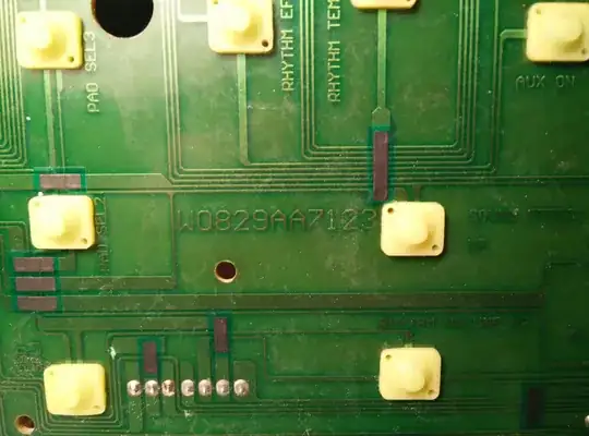
Although I remembered the PCB to have next to no markings (mostly just repeating the button labels), I did find this marking. Not sure if the second character is a zero or a capital o. Google turns up nothing either way, but who knows, maybe someone will find it useful.

serial number found on the PCB

Finally, an example of why I am uncertain about the quality of this particular PCB.

mouse bites of dubious quality

  • Re: "I'm wondering if it's feasible to generate a signal from the oscillating magnetic field of the speaker (similar to how an instrument pickup works). " That's a rather terrible idea, sound-quality wise. You might as well go with mic against the speaker. Please post a pic with the insides of this thing (preferably two: front and back of the board). I doubt it is as flimsy as you say if the board takes a TO-220 package (the TDA2030). – Fizz Oct 03 '15 at 18:32
  • To detail my first point. Instrument [pickups](https://en.wikipedia.org/wiki/Pickup_(music_technology)) rely on mechanical vibration of the case they're on (they don't pick up external EM fields), but for said instruments the case vibrates "nicely". For a speaker the case is designed *not* to vibrate. Well, for crappy ones it does vibrate but, it's nothing like the vibration that comes out of the speaker cone. – Fizz Oct 03 '15 at 18:40
  • And the cone is too flimsy to put a pickup on it. – Fizz Oct 03 '15 at 18:57
  • I believe a DI would do the trick. If it is only for a joke, remove the speaker connection and wire the output of the amplifier to a 1/4" TS... straight into his amplifier. Note that the volume in the toy should be pretty low! – Claudio Oct 03 '15 at 19:53
  • 1
    What do you see that makes you so uncertain of the quality of the PCB? Looks pretty typical to me... – Matt Young Oct 04 '15 at 01:16
  • @RespawnedFluff: I think only Piezo pickups (for acoustic instruments) are reliant on mechanical vibration. The "Magnetic pickups" section of the wiki page you linked says: "The permanent magnet creates a magnetic field; the motion of the vibrating steel strings disturbs the field, and the changing magnetic flux induces a voltage in the coil." The speaker has a pretty sizable permanent magnet, I the cone is driven by modulating its magnetic field (probably by an electromagnet), which could induce voltage in a coil. –  Oct 04 '15 at 01:24
  • Yes, but did you read the rest? Do you have strings in that thing? Not an applicable technology. – Fizz Oct 04 '15 at 01:30
  • @RespawnedFluff: maybe I was unclear on this, but I didn't mean using a guitar pickup on the speaker. Those of course rely on the string to create the alternating magnetic field for their coils to generate signal from. Here, the speaker already has a magnet, and its field is already being modulated (by the amplifier driving it). So to me it seemed like a coil should respond the changes in magnetic flux. Nonetheless, it could not possibly be simpler than using the TDA's output directly as you suggested. –  Oct 04 '15 at 01:53
  • So after looking at [that](http://i.imgur.com/FUYPWWO.jpg) image more closely, are you sure the speaker wires are coming straight from the TDA2822 output? What's in that blob of glue where the speaker wires come out? They might be two transistors (in push-pull), so there might be more power going out. (There are 4 more tranzitors toward the middle of the board, I'm not talking about those.) Also what's the power supply for this toy (voltage, amps)? – Fizz Oct 04 '15 at 02:00
  • As far as I can tell, nothing's in the glue. Looking at the other side though, each TDA output is connected to the speaker wire as well as a resistor and capacitor in series. I'm adding this info to the closeup of the TDA chip. –  Oct 04 '15 at 02:19
  • I forgot to mention the power supply: 5 AA batteries, so 7.5 volts and... however many amps those produce without exploding so far. –  Oct 04 '15 at 14:43
  • Just tap at the speaker terminals. There's no need for any of this elaboration. – user207421 Oct 04 '15 at 18:57

2 Answers2

3

Given the vastly changed info... TDA2822 is a low power chip (under a 1W; its datasheet recommends it for "portable cassette players"), and of course the speaker it sends to is only 2.5W (doesn't get that much). Basically you can take the output of this amp (from the speakers' wires) straight to any professional line in audio equipment. It's like plugging in a walkman. No divider or anything like that is needed. Professional equipment accepts "hotter" signals than the consumer ones; see line level. Check with a voltmeter just in case that you don't get way over (say no more than 2V RMS on whatever it blasts the loudest), but there's not much else to do.

Also the quality of the PCB isn't great... but do you want NASA standards in toy using a $0.10 chip? The last image are "mouse bites", but those are normal.

Regarding the power supply info (added in a comment): 7.5V is how they get this chip to make enough sound for a loudspeaker. Likely the TDA2822 output doesn't get to the rails (i.e. it's less than 7.5V peak); most amps can't swing all the way to the rails, typically they can go up to 1V or 2V under. Some of the more dinky mixing consoles I've seen the innards of have only 6.3V rated caps on inputs; that mixing console was powered from 6V. So... there's potential danger of damaging a mixing console over a long period of time if this toy outputs to its max volume; we're not talking about immediate fireworks. If the mixing console is powered by more than 6V supply chances are good it uses higher-rated caps on inputs so the danger of damage becomes practically nil. If the mixing console is a profi one it will have maximum input level somewhere in its (service) manual. For example, a TASCAM I have specifies maximum input level as +18dBv (8 V).

Fizz
  • 14,355
  • 2
  • 43
  • 97
  • They're fairly _coarse_ mouse bites is what I was getting at. I don't know though, maybe it's just that I've had to work with Arduino boards a lot lately and I've been spoiled. –  Oct 04 '15 at 01:59
  • @carouselambra: I've added a paragraph after reading the power supply info you've added. – Fizz Oct 04 '15 at 15:20
2

You have a few possibilities but here's the simplest.

The TDA2030 is a single amplifier chip. The amplifier drives one speaker terminal through a DC-blocking capacitor and the other speaker terminal is connected to ground. If a split power supply (+ com -) is used the DC-blocking capacitor may be omitted. If the device has no earth connection (i.e., the internal circuit is floating with respect to ground) the solution should be easy enough.

Play a sustained note or noise on the device and measure the speaker voltage with an AC multimeter. Let's say you read 5 V rms. You need to reduce this to around 0.5 V rms to avoid overloading your external amplifier so you need to set the ratio of R1 / (R1 + R2) = 0.1 - about 9k in this case. Pick the nearest standard value.

schematic

simulate this circuit – Schematic created using CircuitLab

If you want a potentiometer then replace R2 with R3 and choose a logarithmic pot rather than a linear one. If the signal level is too low for the amplifier then reduce R1 to one half and try again.

Transistor
  • 168,990
  • 12
  • 186
  • 385
  • Since the chip turned out to be a TDA2822L instead, I have started a [new question](http://electronics.stackexchange.com/questions/193701/tap-signal-from-tda2822l-convert-to-line-and-instrument-level). I'd really appreciate if you would check it out. –  Oct 06 '15 at 00:53