2

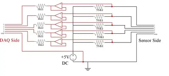
I am trying to design a circuit that uses OP Amps as voltage followers for use in a sensing circuit. The circuits ultimate purpose is the sensor side would be placed in water. The sensor would then be used to detect voids in the water. With the voids being open circuits ideally causing the OP amps to output max voltage and outputting close to 0 volts when the sensor is "shorted" by water.

Schematic

I thought my above circuit would work but it keeps inconsistently either doing the opposite or not working at all. Is it something wrong with the OP Amps (TL074) I'm using, which I find it hard to believe that all 10 of the ones I have are bad, or is my circuit just not designed right?

EDIT 1: The way we were testing the circuit for now was simply by shorting each channels to ground and reading the DAQ output. I.E. Shorting channel 0 to Ground on Sensor side and reading between 0 and ground with a voltmeter. Haven't used actual water yet as we figured it was essentially the same.

We're using +/-15V for the Vcc for the Op amps as well since I forgot to include that earlier.
Wi1D_K4rD
  • 21
  • 2
  • You need to add more details about what you're measuring. Water can have variable and even unpredictable resistance depending what's in it. Hopefully you're not using just distilled water. – Fizz Oct 01 '15 at 14:39
  • What power rail does the op-amp have? – Andy aka Oct 01 '15 at 14:45
  • " it keeps inconsistently either doing the opposite or not working at all" is not a useful description. When you short a sensor to ground, what voltage do you get on the DAQ side? When the sensor is not shorted, what voltage doe you get on the DAQ side? Plus, is the sensor ground connected to the op amp power supply common? That is, the zero volt point where the +15 supply and the -15 supply connect? – WhatRoughBeast Oct 01 '15 at 15:37
  • 2
    Measuring the conductivity of water with DC doesn't work very well. You get all this chemistry going on at the electrodes. Try AC. – George Herold Oct 01 '15 at 17:05
  • 1
    What George Herold said ... here is one possible circuit: http://electronics.stackexchange.com/a/77005/25328 which could be expanded to more channels using a larger microcontroller. – Tut Oct 01 '15 at 17:13
  • Still need more info - how much water are we talking? Are these sensors close together? What type of water? As Respawned Fluff mentioned, here's hoping it's not distilled. – Kikanaide Oct 02 '15 at 19:02
  • I once had an engineering manager critique my circuit who instructed me to "remove all one megohm resistors". His concern was that the least bit of contamination on the PCB would make the 1M resistors not 1M anymore. This sort of contamination can be invisible, and can reside under surface mount components. If you still want to use 5M resistors, go with through-hole, then coat the (scrupulously clean) board. A better option, though, is to take George Herold's suggestion and redo the circuit accordingly. – Otto Hunt Oct 06 '15 at 20:17

1 Answers1

1

You have enough input bias current (5/5MΩ = 1uA) for it to work. The problem is the other unseen elements of the circuit. If this is a tank, you have many other common mode noise sources that could ruin your measurement (AC mains, RF). It won't take much for a few uA's to get into the water and conduct into your sensor and out through other points in the circuit. (A ground loop is also created by connecting the circuit to the water). You might (long shot) be able to get this working if you isolate the circuit from the DAC and earth ground and shield the circuit from external noise. Otherwise go back to the drawing board. Do you really need the DAC if its just an on\off?

Voltage Spike
  • 75,799
  • 36
  • 80
  • 208