9

I'm using a combination of opto-triac + TRIAC to control a 230V AC motor with a microcontroller. For detecting the zero-crossing of the voltage I'm using another optocoupler. opto-triac + triac + snubber optocoupler for zero-crossing detection

I know that the AC motor is an inductive load so the zero-crossing of the voltage comes before the zero-crossing of the current. My circuit senses the zero-crossing of the voltage, but the TRIAC turns off when the current is zero. When should I fire the TRIAC's gate to obtain an arbitrary motor speed (let's say half the normal speed)? How can I know when the TRIAC turns off?

stevenvh
  • 145,145
  • 21
  • 455
  • 667
m.Alin
  • 10,638
  • 19
  • 62
  • 89

4 Answers4

5

You need to know when the AC line zero crossings are. Unlike what others are saying, you are looking for the voltage zero crossings when turning on the triac. This should be obvious when considering the triac is not yet on and therefore the current is zero.

You seem to be trying to measure the voltage zero crossings with the bottom circuit, but you may have to do some experimenting to get it to work well. You are counting on the voltage being low enough to not turn on the LEDs at each zero crossing, which then turns off the transistor each zero crossing. You therefore hope to get a small positive glitch each zero crossing. Getting the LEDs to be off long enough for the transistor to turn off enough for the pullup to work, and then have all that happen with little phase delay is going to be tricky.

In one case I had to do this, I used two optos in push-pull configuration. The LEDs were wired back to back, so each was on for 1/2 each line cycle. The outputs were wired so that one pulled high and the other low. The resulting output was a nice clean square wave with 50% duty cycle and the edges very close to the zero crossings.

In any case, once you have a signal per zero crossing, you simply add a variable delay before turning on the triac. The delay can be from zero to almost half a line cycle. The longer the delay, the lower the overall average voltage to the motor. If the line frequency is 50 Hz, then a whole cycle is 20 ms, and a half cycle is 10 ms, so the variable delay period should probably be limited to 0-9 ms or so.

You will have to experiment to determine the average voltage the motor will see as a function of the delay. You could calculate this if the load were known. Your load has a unpredictable inductive component, so the triac will actually turn off somewhat after the next voltage zero crossing. This delay will itself vary as a function of your turn on delay and as a function of what the motor is doing. If your turn on delay is small, then the inductor gets most of the half line cycle to charge, so will take a while to discharge. If your delay was long, then the inductor was only charged for a short time at low voltage, and will therefore take only a short time to discharge and reach the zero current level where the triac will turn off.

For low apparent motor voltages (long turn on delays), the turn off lag doesn't matter since the triac turns off before you attempt to turn it on again near the end of the next half cycle. As you turn up the motor drive, and therefore decrease your turn on delay, eventually the inductor zero current occurs after your turn on signal for the next half cycle. The triac will now be on the whole time, meaning you motor sees the full line voltage. Shorter turn on delay wont increase the motor drive. However, you still have a nearly full range of control over the motor, just that it's not spread evenly over the whole line cycle. Small turn on delays are the same as continuously on.

Note this assumes that the triac is driven continously from your turn on delay until near the end of the half line cycle. This guarantees the triac is on during the on phase of each half line cycle, regardless of what the current is doing. If you don't do this and instead drive the triac with a short blip after the turn on delay, then two bad things will happen. First, when the motor is full on and the current zero crossing from the previous half cycle occurs after the turn on for the next, the triac will then turn off at that zero crossing. Second, the triac can turn off when there are short glitches in the current, as can happen with mechanically commutated motors.

Olin Lathrop
  • 310,974
  • 36
  • 428
  • 915
  • 1
    One thing you may want to look at is picket-fence firing the triac. Block firing (simply driving the gate low) isn't as effective as driving the gate low with a ~20kHz square wave. Putting a small (.01 to .1uF) capacitor in parallel with the gate resistor will give you a nice high-current rising-edge on each of those pulses which helps whack the triac on. Experiment with the gate R/C to obtain a short high current front edge, with a lower current "back porch" on each pulse. – akohlsmith Sep 14 '11 at 02:57
  • @Andrew: Yes, good point. The important thing for the OP to remember is to keep driving the triac on somehow during the on-time. This will keep it on accross the current zero crossing should the inductive lag be high enough, and will also keep it on accross short current glitches, like can happen with mechanically communated motors. – Olin Lathrop Sep 14 '11 at 11:30
  • @akohlsmith can you develop a little _"Block firing (simply driving the gate low) isn't as effective as driving the gate low with a ~20kHz square wave"_ ? Thank you – rom1nux Dec 05 '19 at 16:19
5

How can I know when the TRIAC turns off?

When the triac is on, the voltage across the triac is clamped to a voltage near zero. (The data sheet for your triac might say something like worst-case V_A1_A2_on is +- 1.5 V).

Many circuits detect when the voltage (positive or negative) across the triac is above roughly +10 V or below roughly -10 V, to indicate that the triac is definitely off. See Figure 4 of AN307.

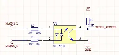
Have you considered possibly sensing the voltage across the triac, like all zero-crossing solid-state relays do, rather than sensing the line voltage, which no solid-state relay does?

When should I fire the TRIAC's gate to obtain an arbitrary motor speed (let's say half the normal speed)?

For a few loads, the speed is roughly proportional to the triac on-time. For these loads, turn on the triac 1/2 the time (turn the triac off 1/2 the time) to get a speed close to half the maximum speed.

More often the load increases as the square of the speed (for example, when pushing a vehicle through the air). For these loads, turn on the triac 1/4 the time (turn the triac off 3/4 the time) to get a speed close to half the maximum speed.

Nearly always there is some minimum on-time (maximum off-time) just to get things moving; anything less than that and some electric power goes in, but nothing moves.

As Olin Lathrop mentions, it is often adequate to experimentally measure the output speed vs. triac on-time a few times (perhaps for 1/5, 2/5, 3/5, 4/5, of the full on-time or full off-time), figure out which setting gives close to half-speed, and hope it stays approximately the same when you run open-loop.

If precisely maintaining some particular speed is important, you may want to run closed-loop -- in other words, add some sort of tachometer to measure the actual speed at all times, and close the loop by adding something to automatically increase the on-time (decrease the off-time) when the measured speed is too low, etc.

When should I fire the TRIAC's gate when controlling an inductive load?

Please consider doing things in the way recommended by the data sheets and app notes provided by the manufacturer, in this case ST application note AN307: "Use of triacs on inductive loads".

Perhaps the simplest approach is

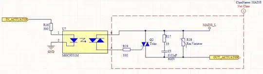
  • watch the voltage across the triac (between pins A1 and A2). When that voltage goes above +10 V or below -10 V, the triac is definitely off.
  • After we sense the triac is definitely off, delay some time from 0 (full-speed) to nearly 10 ms (nearly motionless), then pull the gate LOW.
  • Keep pulling the gate low for some time, until the triac appears to turn on (until the voltage across the triac is small). Then pull the gate HIGH (set the gate voltage the same as the triac A1 pin voltage).
  • Repeat.
Niko
  • 105
  • 3
davidcary
  • 17,426
  • 11
  • 66
  • 115
1

You need to detect the current zero-crossing rather than the voltage zero crossing.

The most straight forward way to do this is to put a shunt resistor in series with your AC load and measure the voltage drop across that resistor. This gives you a direct measure of the current flowing. Often you will need to amplify this voltage as you should be using the smallest possible shunt resistor.

From there use this voltage to feed a comparator or similar device to trigger the zero crossing interrupt in your uC.

You will get multiple fires of the comparator as the current cross nears and passes zero so you usually need to include some sort of windowing functionality to handle this.

Mark
  • 11,627
  • 1
  • 31
  • 38
  • Can't I control the speed of the motor with just the hardware I have? – m.Alin Sep 10 '11 at 08:03
  • 2
    That's not entirely true. If your triac is is off, you will not have any zero crossing. having BOTH the current and voltage zero crossings is important if you're trying to accurate control the POWER delivered to the motor, but you definitely need voltage zero crossings to get started. – akohlsmith Sep 10 '11 at 16:30
  • 3
    As Andrew said, you *do* need to know when the voltage zero crossings are. When deciding when to switch on the triac, there is no current since the triac is off, and therefore no current zero crossings. – Olin Lathrop Sep 12 '11 at 20:08
1

I suggest using one of three options. Two (a and b) involve knowledge of voltage ZC only. The other (c) involves knowledge of both voltage and INDIVIDUAL LOAD current [once the motor has attained 'steerageway' and conducts detectable AC] ZCs.

For each option: Use a high-frequency PWM drive for the Triac gate in a 'sweet' polarity (best not quadrant III - either co-phased or negative gate drive is most desirable). Also, thyristor gates do not necessarily require continuous drive, just a frequent reminder to conduct until they get started (i.e, current flows) during a half-wave.

Each option assumes pretty much the same voltage ZC has been computed for speed (bearing in mind that phase control of induction motors is highly inefficient and not much speed reduction is available with reasonable load torque and motor stalling and overheating are common in the best of circumstances).

Experimentation is of course the best determinant but something like 43.2kHz (edit: factor-of-2 mistake)-> 21.6kHz pwm at 25% duty would give one quarter-degree long pulse per degree of 60Hz phase and this can be a power-saver and yet a very authoritative motor driver. Below, the "voltage ZC" terminology could be replaced with your known phase angle every half-wave for a given speed reduction.

Option (a) gate drive pwm active from voltage ZC until just past a computed (or overestimated or experimentally determined) current ZC phase angle.

Option (b) gate drive pwm active from voltage ZC until nearly the next voltage ZC - take no chances.

Option (c) gate drive pwm active from voltage ZC until just past the observed current ZC.

Personally I have used option (a) with much success at full speed. I have done very little with reduced speed via phase control. Only reason not to simply use option (b) is

When I want reduced speed I try to use a DC motor (cheap) or VFD (torque).

I will note that by contrast, in a present retrofit project I am going to attempt speed control using option (a) above and will report any successful findings.