5

I would like to measure the power consumption of an iPhone 4 using a source/measurement unit.

On other devices I am able to connect the SMU directly to the +/- battery terminals, using tape to insulate the +ve battery terminal from the SMU's supply voltage thereby replacing the battery with the SMU as power source.

The iPhone battery connects to the rest of the device using the connector shown below. iphone battery connector

I removed the outer layer of the battery & found that this is part of a small circuit board that is in-turn attached internally to the battery terminals (in blue). iphone battery circuit-board

I figured I could snip these contacts and attach the SMU to the circuit board to replace the battery, but in doing so I seem to have destroyed the circuit board (I assume from a short while cutting the contact)

I have two more batteries to experiment with: What method should I use to disconnect the circuit board from the live battery to minimize the chance of damage?

rupello
  • 165
  • 1
  • 1
  • 7

2 Answers2

1

Knowing Apple it might very well be a "tamper proof" firmware/hardware mechanism that will shut down the board when battery is disconnected from it. I seem to remember some talk of this when researching laptop batteries and replacing the Li-Ion cells (needing to keep power applied whilst swapping to prevent controller board shutdown) though I am by no means certain.
Google will probably throw some light on the matter if you use the correct incantation.

Edit - had a quick look and managed to find this which seems to confirm this protection may indeed be present in many laptop batteries (2nd paragraph)
If you try again with another battery I would maybe follow the the procedure described regarding applying a secondary source through resistor to keep power present at all times.

Oli Glaser
  • 54,990
  • 3
  • 76
  • 147
  • It appears you may be correct about the tamper-proofing: I tried disconnecting the cell while supplying power to the circuit-board but it cut out immediately :-( – rupello Sep 08 '11 at 16:12
  • This is probably an undervoltage protection mechanism rather than a tamper proofing setup. If the Li-Po cell falls below a certain value the cell chemistry degrades to a point where charging it again is risky. The cell chemistry does not recover so there is no need to reset this safety feature in service. Obviously there must be some way that the circuit is prepared during manufacture but this may be proprietary. Circuits that work with removable cells have to reset if the cell voltage is within tollerance. – KalleMP Dec 12 '17 at 00:02
1
  1. Why connect inside the battery? If the phone is the object of your attentions, as you say, then it would seem to make far more sense to determine what the battery "looks like" to the system and to then create a plug that connects to the phone in place of the battery with the SMU powering the plug. You now have a spare plug that you can use in your dead battery.

  2. However, if you still want to bypass the existing battery, read Oli's answer then, consider trying the following. I have done this successfully to replace a Lithium primary battery in a system that was designed to lose its code if battery power was removed.

This method assumes that a battery proper with only a 2 wire connection is used. This could be a 2 or 3 cell battery. However, if two or more cells are used and the inter cell connections re brought out you can still use an altered version of this method

Swapping a live battery.

Needed:

New "battery"or power supply,
variable resistor (say 100 ohms)
Schottky diode able to take system current draw,
soldering iron,
wire cutter,
wire strippers.

Do not short battery leads to each other or from V+ to ground at any time.
Doing so will cause the battery controller to lose power and may also incinerate the battery. Or more.

Method 1. RS&B Will work in most cases.

Either

1a. Set new supply voltage to = old battery voltage if variable.

Connect new supply to battery terminals on PCB.
Remove old battery.

or

1b. Just connect new battery across old if not variable.
Batteries will not usually explode or catch fire.
Not usually!.


Method 2.

The method works by first isolating the old battery with a Shottky diode without losing power to the controller.
The new battery is then ramped up to prevent a surge.
If the new supply voltage is higher than the old one the new battery will take over as Vnew goes to >= Vold Vdiodedrop.
Once the new battery is in position the old battery and diode can be removed.

This method prevents the new battery being electrically connected into the old and minimises voltage surges.

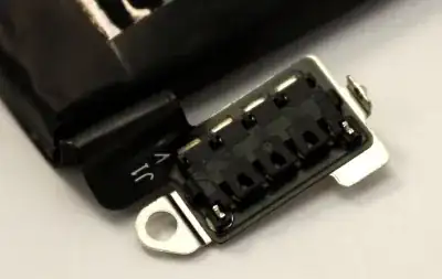
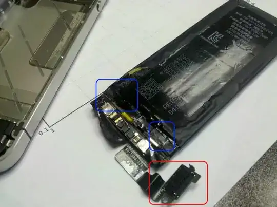
Identify positive and negative leads.

Connect new "battery" negative to existing battery negative - often at common ground point.

Establish two solderable points in old battery positive lead which are both at battery V+. eg battery and V+ on connector, or strip battery lead in two places without

Solder diode between 2 solderable points both of which are at V+. Anode end towards battery. Cathode end towards phone.

Cut wire from old battery somewhere between the two solderable points.
The diode is now in series with the battery.
The phone is now running from Vdiode Volts less than before.
It MAY stop at this point but almost certainly wont.

Connect new battery or psu to ground (V-) directly and to V+ via 100 ohm resistors with resistor set to 100 ohms.

Slowly (over say 10 seconds) reduced resistor to zero ohms.
Bypass resistor with a wire link and remove resistor.

The battery pack is is now running from the new battery or supply.

Cut or break or remove V+ wire from old battery to diode.
(Optionally, instead place resistor set to 0 ohms in series with diode and then increae resistor to 100 ohms). Remove diode and old battery and resistor if used. .

Russell McMahon
  • 147,325
  • 18
  • 210
  • 386
  • Under no load the supervisory circuit should draw very little power. It should be possible to make this battery switch using resistors to do the bridging from one cell to another. However a charged cell will need to be available through a robust diode to provide sufficient current if the PSU mains fails it just wont charge in service and the PSU also needs a diode if it presents a significant load when not powered. Adding a dummy load to test charging characteristics makes the setup rather messy. – KalleMP Dec 12 '17 at 00:07