1

I am using the MSP430F5438A-EP microcontroller. I wanted to know the max current that could be sourced by this chip. The datasheet is -Datasheet.

The data given in page 38 states - Diode current at any given pin = 2mAmps. The diode, I believe, is the protection snubber circuit in each GPIO. Right ? Hence, I am safe in assuming that each pin can source a max of 2mAmps ?
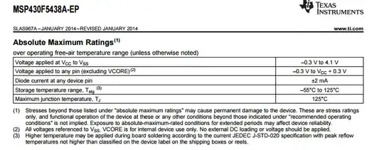
Absolute rating.

Nick Alexeev
  • 37,739
  • 17
  • 97
  • 230
Board-Man
  • 1,919
  • 1
  • 26
  • 70

2 Answers2

3

No. That's how much current will destroy the voltage protection diodes if a voltage above or below the maximum values is applied to a pin.

The maximum current available is described on page 44, in and just below the "Outputs – General Purpose I/O" tables.

Ignacio Vazquez-Abrams
  • 48,282
  • 4
  • 73
  • 102
  • But this gives the total current supplied by the chip. Not the individual pin max current sourcing. I am looking at the max current that can be sourced. – Board-Man Sep 22 '15 at 09:13
  • Also, the chart states some of the test conditions as -3mAmps. What is this negative sign for ? Also, if the snubber circuit (protection dioodes ) are blasted if the current is more than 3mAmps, how can they test it at -3mAmps ? – Board-Man Sep 22 '15 at 09:14
  • @VinodKaruvat the current on page 44 is the current that can be sourced from an IO pin - what other method is there of sourcing current? You asked for "I wanted to know the max current that could be sourced by this chip" and this, as far as I can tell is what you want. – Andy aka Sep 22 '15 at 09:16
  • sorry, wrong chopice of words. my bad. I want to know the max current that can be sourced by any GPIO of this chip. – Board-Man Sep 22 '15 at 09:17
  • 1
    @VinodKaruvat the protection diodes are when the IO is an input. Sourcing current is different to diode clamp current. – Andy aka Sep 22 '15 at 09:18
  • You have your answer @VinodKaruvat – Andy aka Sep 22 '15 at 09:19
  • So, lookingg at the table(Outputs – General Purpose I/O (Full Drive Strength) ) in page 44, what I see is that they have test conditions of -3mAmps,-6mAmps and uppto -15mApms. So, from this I am assuming that although the max current sourcing can be as high as -15mAmps, the sum total cannot exceed 100mAmps. Now, what does this negative sign denote ? Also, in the test conditions of the said table, we see that at Vcc = 3V, I(ohmax) = -5mAmps and a max of 48mAmps, but at the same time at 3V and I(ohmax) = -15mAmps a max of 100mAmps. How is this possible ? – Board-Man Sep 22 '15 at 09:23
  • 1
    @VinodKaruvat: How much current you can source depends on what voltage drop you can tolerate. See the tables for details. – Ignacio Vazquez-Abrams Sep 22 '15 at 09:23
  • As per my previous commen, in both the case the drop is 3V, yest the max current sourced by this chip is 48mAmps and 100mAmps. – Board-Man Sep 22 '15 at 09:28
  • Did you actually read the values in the "MIN" and "MAX" columns? – Ignacio Vazquez-Abrams Sep 22 '15 at 09:31
  • 1
    @VinodKaruvat the max current of 100mA is for the sum total of GPIO pins used to source (or sink) current. Each pin can say source 10mA but no more than (say) 10 pins can be used for doing this. – Andy aka Sep 22 '15 at 09:32
  • And what does the negative sign denote ? – Board-Man Sep 22 '15 at 09:34
  • 1
    http://electronics.stackexchange.com/questions/103894/understanding-74lvc245-datasheet-and-current-source-sink/103900#103900 – Ignacio Vazquez-Abrams Sep 22 '15 at 09:36
2

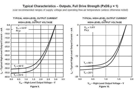
There is no single number. The current depends on supply voltage, high level output voltage VOH, temperature. Fortunately, the datasheet provides curves like this: enter image description here (pp.45-46 in the datasheet)

Related

Similar discussion about MSP430G2210.
Discussion about digital output current in PICs.

Nick Alexeev
  • 37,739
  • 17
  • 97
  • 230