SUMMARY
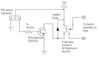
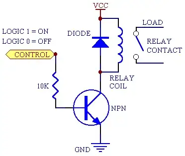
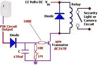
The circuit diagram below shows a basic means of operating a relay or LED
Many other circuits are provided via the reference link
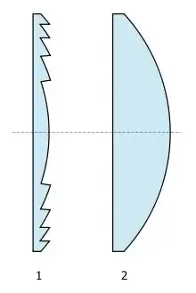
A Fresnel lens or some other lens will be required to allow this detector to function as intended. Links to various explanations of how lensing systems work with PIRs and links to suppliers of typical lenses are provided.
The line in the LHI778 data sheet labelled "output impedance" tells you what you need to know for interfacing purposes.
The sensor is either on or off.
When on and when you use a 47 kohm load resistor the FET looks like it is a resistor with resistance between 5 and 10 kohm.
Looks like load should be from source to ground with drain at V+ - not with load in drain as below. Arithmetic still applies as below.
You can design from there.
eg if you ground FET source and put 47 k to drain from V+ then.
eg if V+ = 9V drain will be from 5/52 x 9 =~ 0.9V to 10/57 x 9 =~ 1.6 V.
This output can be used to drive a transistor or op amp circuit of your choice.
Or an LED plus series resistor could be used in place of the relay coil (LED will have the opposite polarity to the diode shown - remove relay and diode and add LED plus series resistor.). If that advice is not enough and you need detailed circuitry then you probably need to do some more reading on the subject. See references below.
The above circuit is from here
* Many more PIR circuits here *
Fresnel and other lenses for PIR use:
Note that the device by itself is not suitable for your task. You need to add a Fresnel lens or similar optical system that causes changes in input as te detected body moves between "zones". Searching the web for
PIR Fresnel
should turn up many explanations of what is required.
Many many many images plus links to web pages
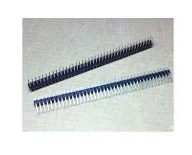
Various PIR components including lenses and sensor ICs
PIR Fresnel lenses and cone optics
Various Fresnel lenses for PIR use
Still more Fresnel lenses
Alibaba - vast range of lenses andelated materials
Wikipedia on PIR detectors
Fresnel lens tutorial
And more ...