Many people, including me are good with dealing with real and reactive power in power flow systems, but still has question at the end of the day: What is reactive power and how it is generated or what is its source? After taking few course in power electronics, I tried to come up with simple explaination of what is reactive power and what is its source.
5 Answers
An AC voltage source will provide real power to a resistor; the voltage is in phase with the current and this means "real watts" are produced by the resistor and you are billed for the energy usage.
Consider an appropriately sized capacitor (or inductor) that also draws the same current from that same AC voltage source. Now, the average power taken is zero and you are not billed by the energy provider.
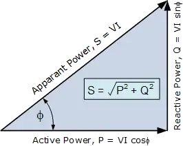
If you multiplied RMS values of voltage and current you get what is known as "apparent power" and for a resistor this is also the "real power" BUT, for a capacitor or inductor this is all reactive power. So you have three terms that are linked mathematically: -
But why does reactive power not get billed i.e. what is so special about the current that flows in a capacitor or inductor compared to a resistor?
Answer - using the capacitor as an example, Q=CV i.e. charge stored = capacitance x voltage. If you mathematically differentiate both sides you get: -
\$\dfrac{dQ}{dt} = C\dfrac{dV}{dt}\$ and rate of change of charge equals current
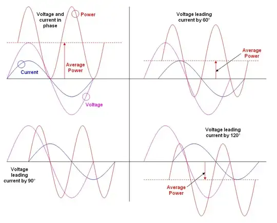
So the waveform of current in a capacitor "follows" the differential of the supply voltage. If supply voltage is a sinewave then current is a cosine wave i.e. (and here's the important bit) it is 90 degrees shifted forward and, if you were to calculate real power you would find, somewhere in the algebra, a cos(wt) multiplied by a sin(wt) and, there can be no escaping that this produces a waveform that has an average value of zero (go do trig!): -
You are billed on average power not peak power or (god forbid) RMS power or even reactive power.
Pretty graph stolen from here. Note that the power waveform is twice the frequency of the voltage or current. For a resistive load, V and I would be in phase and the power waveform would be wholly positive i.e. the blue waveform moves up as red and green become in phase.
See below for several scenarios of current phase displacement relative to voltage and what that means for the position of the power waveform: -
- 434,556
- 28
- 351
- 777
-
Okay, I think I understand. So you're saying that reactive power messes with the calculation of _average_ power, and this is why the power companies want your circuits to have a high power factor as no energy is actually dissipated with reactive power? – jonny Nov 30 '19 at 11:56
-
@jonny that's about right. – Andy aka Nov 30 '19 at 19:25
Reactive power is energy circulating back and forth between the source and the load. Usually the load is an induction motor. Energy stored in the motor's magnetic field is transferred to and from the source every time the polarity of the magnetic field reverses. Alternatively, the energy can be transferred to and from power factor compensation capacitors. That transfer of energy is reactive power.
Real power is energy that has been consumed by the load. It has been converted into another energy form and isn't coming back. Reactive power is simply energy that is being stored in the load by any capacitors or inductors inside it. It can be returned to the source and indeed does so on a cycle-by-cycle basis in linear AC systems.
The terms are just a way to simplify the analysis of AC power systems. They are useful because when we are talking about a motor, heater or light, we really want to know the real amount of power that is being converted by the device, but if you just measured the terminal voltages and currents you would get the wrong answer because of the presence of reactive power.
- 4,894
- 13
- 20
So, this is my view and understanding of power flow:
Simply, think about a generation plant providing power as a main ‘water tank’ supplying water to community. This water tank has two taps.
First tap is only used by people (i.e resistors) for direct usage of water such as drinking, cooking etc. After these people use water from first tap, it’s gone (converted into some other form, but its no longer water anymore)!
The water from the second tap is used to fill small buckets for back up i.e. to compensate for “big air bubbles or temporary outages” in the first tap, assuring people like (resistors) get water all time! People like capacitors and inductors (motors) use this second tap. This water can be used again when required by people like resistor. More importantly, over all, BOTH taps are sucking the actual water out of main tank!! So, answering question, how reactive power is generated? Well, in fact, it is same as how real power is generated! They are both water quantity, nothing else!
Water coming out of second tap can be called reactive water (we symbolize it with imaginary number j), and the first tap is real water. Fortunately, people using first tap do interact with people using second tap. The interaction between people consuming from first tap and second tap is modeled by a mathematical formula (a+jb) so we can realize what is happing in the community with water supply!! The “j” is just used to give each tap a separate identity/label. You can actually put “j” in front of real quantity and not put “j” in front of reactive quantity and still get correct answers! Its just swapping labels on taps. This is the whole point of using imaginary numbers in engineering/math! The quantity associated with imaginary number DOES have physical realization in world. Hope this simplifies things for better understanding of how power stuff works!
- 1,620
- 3
- 22
- 31
-
@Andyaka: The answer you provided is absolutely correct which most electrical engineer would typically understand and follow. I was trying best to explain it without calculations I.e product of voltage and current out of phase. I was asked by few people (not ee background) to explain without all these typical power formulas. – dr3patel Sep 19 '15 at 13:28
-
@Andyaka: as a new person to EE, I found this useful, hopefully it's correct? – rrrrr Jan 29 '19 at 18:08
Another way of understanding reactive power is to think of an undamped mass-spring system.
Let's make an analgy: Power = force . velocity equivalent to Power = voltage . current
So, when you have an undamped mass-spring system with some initial excitation, the mass will oscillate eternally, with the velocity lagging force 90º degrees. Energy is being exchanged from the mass (kinetic) to the spring (elastic) and vice-versa, but no real work is being done on average (you have positive and negative semi-cicles of power).
That's the mechanical analogy for pure reactive power system - in this case a LC circuit, where energy is exchanged between an inductor and a capacitor.
In a single-phase power system, reactive power comes from the interaction of generator windings and any inductive loads on the system, and it's bad because then you have this energy exchange between the load and source going through the whole transmission system, overloading lines and resulting in losses.
When using, for instance, a capacitor for correcting the power factor of the load, you are actually taking the energy ping-pong from being system-wide to being local-wide, nearer to the load - so your losses go down.
For balanced three-phase systems, however, it is important to notice that the reactive power isn't exchanged between source and load, but instead between system phases (yes, from one wire to the other two).
- 546
- 2
- 13


