0

We have dual power supply units (+- 12V DC with common GND) at our college lab using which I am able to implement my project (digital thermometer) which uses op amps as shown in the figure.

I'm using an LM35, three op amps, an Arduino Uno, and an LCD display. I need to make this a product which can be run using only one external power supply (+12V DC adapter for the Arduino).

I tried using a voltage divider circuit to supply +6V and -6V DC to the op amps. However, when I connect the LM35, feedback resistors and other components, the voltages measured at various stages are not as expected. In fact, the input voltage itself changes it's value from +6V to +2V and the other voltage changes to -10V from -6V. One thing I have noticed is that there is a constant voltage difference of 12V between the input pins.

Why am I getting weird values of voltages? Is this called the "loading effect"? What are the other possible ways of supplying power to the op amps using the 12V adapter?
The schematic that works with the dual power supply unit at my college

EDIT: This is the schematic that works with the dual power supply unit (+-12V) at my college. I want to make this device portable. Hence, I can't use the dual power supply all the time. Need a solution for this...

  • Your diagram doesn't match your description. According to the diagram, your op-amps are powered by +12V and -12V, and you have a voltage divider providing 1.3V. If you've replaced the 12V with some voltage divider providing 6V then yeah, you are going to have problems. A voltage divider can't provide power to the op-amps. An unloaded divider can provide a reference voltage, but can't deliver enough current to power an amplifier - the amplifier will act like another resistor in parallel to part of the divider and change output voltage. – JRE Sep 17 '15 at 14:31
  • @JRE I totally agree with you. I just wanted someone to confirm that. The diagram which I've shown is the one which I use in college. It works perfectly fine. The voltage divider output is given to the summing amplifier because the transfer function of my application requires a constant voltage of 1.3V to be added to the output. Anyways, you cleared my doubt! Thanks. – Navin Sridhar Sep 17 '15 at 14:37
  • In general, when asking a question, you should show the circuit that doesn't work, not a different one that works. – Pete Becker Sep 17 '15 at 16:29

2 Answers2

2
  1. The µA741 can be used in single voltage applications.
  2. The 741 is pretty lousy as far as op-amps go.
  3. There are better op-amps that work better on single voltage supplies.
  4. You cannot power an op-amp from a voltage divider (insane things like two 1 Ohm resistors excluded.)

What you need to do is to look up single voltage operation for op-amps, and see what you need to do. Hint: It does involve a voltage divider, but not powering the amp.

Here is an example of a 741 running on a single voltage: enter image description here

JRE
  • 67,678
  • 8
  • 104
  • 179
  • I've got an LM324 and an LM358 too. Since two of my op-amps will be used in the inverting configuration, I don't think I can go ahead with using single supply as it will clip the negative output. – Navin Sridhar Sep 17 '15 at 14:45
  • 1
    No, it won't. You work around a virtual ground that is at 1/2 of VCC. So, with 12Volts, you have a virtual ground at 6Volts. – JRE Sep 17 '15 at 14:48
1

What are the other possible ways of supplying power to the op amps using the 12V adapter?

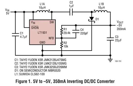
You can use an inverting switching regulator like this: -

enter image description here

The one above takes +5V in and produces -5V out but equally you can use the same device to convert +12V into -12V. Read the data sheet of course.

Andy aka
  • 434,556
  • 28
  • 351
  • 777
  • This seems to serve my application well, but this IC uses way too many extra components. The 7660 is another IC I'm planning to use. – Navin Sridhar Sep 17 '15 at 14:43
  • 1
    @NavinSridhar Well, your design uses two op-amps that are basically redundant along with 4x 10k resistors and no-doubt op-amp decoupling capacitors so how do you justify your "way to many extra components"? – Andy aka Sep 17 '15 at 14:48
  • I have an LM324 which is a quad op-amp IC. I also had the option of using a single op-amp in the difference amplifier config. But it doesn't have very good repeatability and doesn't offer accurate gain all the time. I think the 7660 can't provide high current, so I might as well go with this DC-DC converter. I'm just waiting for better solutions. – Navin Sridhar Sep 17 '15 at 14:55
  • 1
    The LM324 sounds a better idea than dinosaur crappy 741s. I'm 57 and I have been doing analogue stuff for near enough 40 years and I've never used a 741 in all that time and there's a reason... did I say they were crappy LOL. – Andy aka Sep 17 '15 at 15:00