0

I have an iPhone project , I need to turn on and off a led powered with a battery using iPhone via 3.5 mm jack.

there is some examples what I need

https://www.youtube.com/watch?v=w0VopnVZQ-w

http://www.ipinlaser.com

I need suggestions. I know some simple basics on circuits but I'm totally noob about this.

Memik
  • 1
  • 1
  • 3
  • Are you developing the app yourself? It looks like the guy in the video pretty much bought something that is no more than an LED soldered to a TRS plug. – Nick Williams Sep 10 '15 at 12:46
  • Yes i will develop the software. Actually these samples creates a sine sound wave and activating the led. I made a research, some of them used some resistors and transistors in the circuit. I just need a circuit diagram to complete this project – Memik Sep 10 '15 at 12:51
  • And you are using a battery external to the iPhone that is intended to power this LED? I'm just trying to get a feel of what your exact expectations are. – Nick Williams Sep 10 '15 at 13:03
  • Yes led is powered by an external power source, i will use iPhone like a switch that to turn off and on the led – Memik Sep 10 '15 at 13:48
  • This topic has been [covered here before](http://electronics.stackexchange.com/questions/26785/power-led-from-headphone-jack) although the answer there was also tentative (but looks more promising than the one below.) – Fizz Sep 11 '15 at 03:58

1 Answers1

1

I'm not that great with Android App development so I'm assuming you can make the headphone jack output a voltage in reference to the "common" ring. This guy got his android to output a waveform that was dependent on the accelerometer device readings.

Most smartphones have TRRS jacks on them, where the breakdown looks like this:

enter image description here

So if you can control the voltage difference between "Left" or "Right" and "Common", then you could exploit that.

Have the voltage difference feed into a transistor, while your external battery drives your LED. This is a much better method because you don't really want your phone to drive your LED, you just want it to say "OK, turn on, now turn off" etc.

schematic

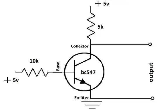
simulate this circuit – Schematic created using CircuitLab

So it's just a really simple circuit, where the phone activates/deactivates the transistor. When the voltage of "LEFT or RIGHT" goes HIGH, current will travel from the battery, through the transistor and through the LED. Setting the voltage to ground will stop any current from flowing.

Nick Williams
  • 1,815
  • 3
  • 17
  • 29
  • 1
    You cannot send a DC voltage out the earphone jack. Doesn't work. You would have to send out and audio signal. Best case, your LED blinks real fast - if you put out a high frequency (>100Hz) tone then you wouldn't see the blinks. You'd have to use full volume, though, and put the transistor below the LED instead of above it. The way you've done it, the signal from the phone has to be higher than V1. – JRE Sep 10 '15 at 16:08
  • Yeah, I was kind of thinking he could output some sine waveform and get a sort of PWM effect; however I tried to ignore that thinking because I wanted to abstract the android end from what the circuit end could be. – Nick Williams Sep 10 '15 at 16:12
  • @JRE: Maybe the one on the iPhone can! (joke). More seriously, you need to rectify the AC sound signal before feeding it to the transistor's base. Since efficiency isn't really a concern, a half-wave rectifier should do it. – Fizz Sep 11 '15 at 00:45
  • Come to think of it a bit more, you probalby need to amplify the audio signal a bit first (with another transistor), because there probably won't be enough voltage left after rectification otherwise, even with a Schottky. Measuring my non-iPhone Android phone, it maxes out at 0.68V peak on audio... Alternatively, build a charge pump and charge the capacitor one more than one cycle. – Fizz Sep 11 '15 at 01:22
  • 1
    More here: http://electronics.stackexchange.com/questions/28971/how-to-trigger-a-transistor-from-iphones-audio-output-jack – Fizz Sep 11 '15 at 04:18
  • @RespawnedFluff: There's no need of a separate diode. The base of the transistor provides all the rectification needed. – JRE Sep 11 '15 at 06:57
  • @JRE if you want the led to flicker then yes. See simulation: http://imgur.com/Ti29fuX By rectifying I was thinking of rectifying and filtering (diode + cap). However, with stereo audio one might sent 180-degrees phased signal through the other channel as a substitute. – Fizz Sep 11 '15 at 11:08
  • With 2 transistors fed out-of-phase signals, it might work better, but there's still potential flicker http://imgur.com/U88JLIY. I suspect the degree of flicker it depends on the led used. This needs breadboarding. – Fizz Sep 11 '15 at 11:23
  • Do note however that if I set the signal sources to just 0.5V peaks (instead of 1.5V as above), that's not enough to turn on the transistors anymore. And if the other threads linked here are correct, that's all some iPhones can dish. – Fizz Sep 11 '15 at 11:31
  • @RespawnedFluff: You won't see a flicker if your audio signal is above 100Hz. Make it 1kHz or more and NOBODY will be capable of seeing it flicker. – JRE Sep 11 '15 at 11:37
  • @JRE perhaps, but the voltage issue seems to be a real problem. http://electronics.stackexchange.com/questions/69834/how-do-i-amplify-a-dc-voltage-that-is-too-weak-to-trigger-the-base-in-a-transist – Fizz Sep 11 '15 at 11:37
  • The audio out level could be a problem. A separate rectifier won't help there, though, either. So, you make an audio amp out of one transistor to raise the voltage then use that to drive the transistor controlling the LED. – JRE Sep 11 '15 at 11:40
  • Probably the most tunable solution is provided here: http://electronics.stackexchange.com/a/155914/54580 – Fizz Sep 11 '15 at 11:53