I'm currently considering a design for a linear regulator that uses some input resistance to help it regulate a higher current than it could handle on its' own.
It's not a hopeless plan. Increasing the radiating surface area effectively lowers the system's overall thermal resistance.
That said, there's no free lunch. Dropping some of your excess voltage across an additional resistor just shifts part of the heat generated to a different part of the board. If the resistor is close to the regulator, it will heat up the air next to the regulator and thereby likely fail to give you the benefit you want: device temperature is a function of thermal resistance, and thermal resistance is always relative to ambient temperature. Raising ambient temperature eats into your thermal budget the same way excess voltage does.
Another big downside of your plan is that the resistor will create additional current-modulated ripple for the linear regulator to remove. That is, if your load current is varying by ±5 mA at a rate of 1 MHz, sticking a 100 Ω resistor in series with the regulator will create an additional 1 V of pre-regulator ripple. Worse, linear regulator effectiveness drops as frequency goes up, so that your regulator might let much of this ripple sail right through.
(Look for the ripple rejection vs frequency graph in your regulator's datasheet. One 78L05 sheet I have here says RR is down to ~20 dB at 1 MHz from ~55 dB at 60 Hz. A 35 dB difference means it is letting 57× more ripple through!)
You can avoid generating current-modulated ripple by dropping the excess voltage across a low-impedance stage instead of a resistor: several diodes in series, an extra pass transistor, a second linear regulator, a DC-DC converter, etc. The latter option is fairly common, actually: a DC-DC converter to get the voltage into the right range, followed by a linear regulator to reduce the hash put out by the converter to acceptable levels.
Does anyone know of a better treatment of the thermal characteristics of chip resistors?
Any good resistor datasheet should include a power vs temperature graph, like this one:
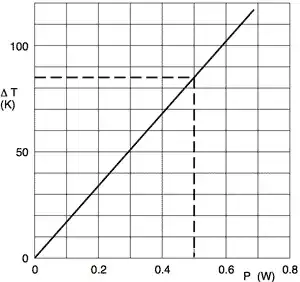
This is for a nominally ½ W resistor, showing that you should expect an 85°C rise over ambient at its rated limit, or about 110°C in free air at room temperature. Inside an enclosure surrounded by room temp air, the air will be warmer, so you can make a first-order guess that this resistor should never run hotter than about 125°C.
A good datasheet should also include thermal resistance numbers, expressed in degrees per watt. From those, you can calculate the effect of cooling on the resistor's temperature, which then feeds back into that graph to tell you whether you're running the resistor too hot.
What does the power rating of the chip really mean?
It's just a nominal value, not a hard limit. That's why it's shown as a dotted line in the graph above, with the graph extending above and below that "limit." That graph says that if you can arrange to cool the resistor somehow, you can run it over the rated wattage. But equally, if the resistor is inside a hot enclosure, you have to derate it.
Is it soldered onto a board?
That certainly affects things. If you use wide, heavy copper traces (say, 100 mils wide on a 2 oz copper board) you get some heat dissipation in the traces, which might let you run the resistor a bit hotter than otherwise.
A proper heat sink is a better solution than thick copper traces.
Your datasheet is almost certainly giving values that assume no significant cooling from the nearby copper, unless it specifically talks about the copper. Some datasheets actually give you recommended copper patterns and their expected thermal resistance values.
