12

I have a 3-wire load sensor that looks like this:

Three wire load sensor

I'm trying to wire it up to my Arduino to detect changes in weight. From what I understand, the changes in voltage are so small that the Arduino can't detect the changes without amplifying the voltage. So I bought an 8-pin LM741CN Op-Amp at Radio Shack that looks something this:

8 pin Op-Amp amplifier

I found this video that shows how to wire everything up. However, I can't figure out the schematic and why they are using two load sensors instead of just one. They also mention resistors but I'm not sure why they are using them (and why the sizes they chose), or where in the circuit to put them.

Can someone please help me figure out how to wire this thing up to detect changes in voltage? Also, is there a way to do this by using only one of these sensors? This is what I've done so far:

Arduino load sensor diagram

The amp also has some pins that I don't understand: Offset null, NC. What are these pins for? Should I be using them?

Update: Now I am working with an Instrumentation Amplifier (AD623). I also now have a 4-wire load sensor that I am playing with. Still can't get it to work, but I thought I would try to understand that before moving to the 3-wire load sensor.

Andrew
  • 285
  • 2
  • 3
  • 11
  • 2
    Your sensor is almost certainly a "half bridge" of two strain gauges - they form the right hand two resistors in Steven's first diagram - ie "R2" and "strain gauge" as he has them labelled. One wire will be the top of bridge connection, one the bottom of bridge connection and one will be the common connection between the two. Measuring between two wires at a time common to top and common to bottom will be the same resistance. eg name wires T B C (top bottom common). T to C = R, B to C = R, T to B = 2R. Connect common to right hand middle of bridge, connect T & B to top and bottom. – Russell McMahon Aug 27 '11 at 07:00
  • 1
    I agree, looks like a half bridge, and the wiring in the diagram looks okay. Just the resistors (and maybe bypass/compensation caps - in the instrumentation amp question we discovered it was oscillating..) are missing. Confirming beyond doubt the part number (i.e single/dual) would be useful. – Oli Glaser Aug 27 '11 at 11:01
  • @OliGlaser -- Swap the excitation for one of the gauges. As-is it is measuring the difference between the two gauges. If the the OP wants to measure the changes to the sum of the weight applied to the pair of gauges, they should be setup to increase the unbalance as they load up. – Dave X May 04 '23 at 01:31

5 Answers5

13

The strain gauge is a variable resistor, so your first idea may to build a resistor divider with a second, fixed resistor to detect the variations as a change in voltage.
Unfortunately strain gauges are very insensitive variable resistors, whose resistance changes only very little when weight is applied to them. A resistor divider is not nearly sensitive enough to detect the changes. So we need another approach.
A Wheatstone bridge is the solution.

Wheatstone bridge

The strain gauge together with R2 still form a resistor divider, so how is this different? Let's assume that all resistors have the same value, equal to the strain gauge's resistance at rest. Then the voltage across the voltage meter will be zero instead of half the power supply. Since our reading is zero referenced we can amplify it easily to get a higher sensitivity for the complete circuit.
Oli mentioned the differential amplifier, but this isn't going to be enough. We don't want to affect the reading by putting a load to it, like the differential amplifier would. We need an instrumentation amplifier, which is a differential amplifier with a very high input impedance. This is the most used instrumentation amplifier configuration,

enter image description here

which uses a single resistor (\$R_G\$) to set the amplification. You'll have to set the amplification to a high value, possibly somewhere between \$\times\$100 and \$\times\$1000 (not very clear; the so-called strain gauge datasheet simply stinks).

Now, how do we connect the strain gauge, because it has three wires, not the two like in the above schematic? Again the datasheet is no use here, but you probably connect it like this:

enter image description here

This way of connecting compensates for the wire resistance \$R_{WIRE 1}\$, which otherwise would affect the reading.

Another possibility is that the wires represent the top, right and bottom point of the Wheatstone bridge, resp. Which one it is can be easily determined by measuring the resistance between wires. In the first case you'll have no resistance between \$WIRE 1\$ and \$WIRE 3\$. In the second case you'll measure an equal resistance between red-white and white-black (you may have to switch wires. Again, the datasheet doesn't help).

You connect the voltage meter connections of the Wheatstone bridge to the inputs of the instrumentation amplifier.


images from this website

stevenvh
  • 145,145
  • 21
  • 455
  • 667
  • Thanks for your answer. I'm still totally confused though. I don't understand how to read those schematics. What does the V with the circle around it mean? Do the zig-zag lines mean resistors? What sizes are those supposed to be. Where is the amplifier in your last schematic? How would I connect that circuit to the amp? – Andrew Aug 29 '11 at 05:00
  • @Andrew - The V in the circle is the symbol for a voltmeter, here it indicates between which two points you'll measure, so those points are the inputs for the instrumentation amp. The zig-zag lines are resistors. R1 = R3, exact value not really important, take for instance 10k. Your R2 is possibly part of the sensor, then you connect the 3 wires to top, right and bottom of the bridge. – stevenvh Aug 29 '11 at 06:21
  • I think I missed the part about the "instrumentation amplifier". I didn't realize it wasn't the same as an Op-Amp. I should probably start there before trying to waste my time wiring up something that won't work. Where can I buy a few of them? And which ones would work best for my application? – Andrew Aug 30 '11 at 00:27
  • @Andrew - You can buy integrated in-amps, like the [INA128](http://www.ti.com/lit/ds/symlink/ina129.pdf), but they're expensive. You can also build them yourself from 3 op-amps, but I wouldn't use 741s for it. A quad op-amp like the [LF347](http://www.ti.com/lit/ds/symlink/lf347.pdf) is a much better choice. For sale at every decent electronics shop. Online at Digikey or Mouser for example. – stevenvh Aug 30 '11 at 06:07
  • I now have an instrumentation amp (AD623) to work with. I also now have a 4-wire load sensor that I am playing with. Still can't figure out how to wire it up (specifically, how to set the gain on the in-amp), but I thought I would try to understand the 4-wire before moving to the 3-wire load sensor. Could you help me understand how to wire up the load sensor to the in-amp and set the gain? – Andrew Sep 21 '11 at 19:50
  • The load sensors in the picture are half-bridges with two strain gauges, one on a positive strain part of the metal, and one on a negative strain part of the metal. One half bridge could be R1 &R3 in your 2nd diagram, and the other could be R2 and the other strain gauge, with (V) across the green wires. The trick is to flip one of the half-bridges so that positive load on the pair pushes one signal + and the other signal negative so the difference across (V) becomes more unbalanced as the load increases. – Dave X May 04 '23 at 01:04
8

I won't comment on the circuit design, as that seems to be getting plenty of attention, but I built a project where I hacked a bathroom scale so it was network enabled and has a web server to to serve the current weight, and I have a few thoughts on putting the whole thing together.

Before you build your amp, in order to get a rough idea of how to set the gain, build the strain gauge circuit first, power it up, and use a multimeter (which is much more sensitive than your Arduino's ADCs) to measure the output voltage from your strain gauge circuit with the maximum expected load applied. Then when you build your amplifier circuit you can select gain resistors that bring the amp's maximum output to 5V (the Arduino's ADCs sample 0-5V), and you will get the most range out of your ADC.

The reason to do this is that the range and resolution of the ADCs is limited and discreet, so if you want to measure 0-1000 pounds, with the 10-bit resolution of the AVR's ADCs, you would at best be accurate to within a pound if your amp's output signal goes from 0-5V as the weight increases from 0-1000 lbs. If you just half-ass it or guess with the gain resistors, or start with pure trial-and-error and get bored and don't use the full range, you will throw away accuracy. Say you cobble together an amp and it only puts out 0-2.5V, then you will be throwing away half the range and only accurate to within 2 lbs. for that same 1000 lb. range.

It depends on the project and how much you care though. When I built my hacked scale I needed a range of 0-200lbs., but I wasn't very concerned with accuracy. Basically my goal was to determine whether a container on the scale was empty or full, with maybe a very low resolution beyond that like 1/8 full, 3/4 full, that kind of thing. I just built the simplest single opamp differential amplifier circuit I could find with the first low-voltage opamp I had in my parts bag, with the gain set so that it saturates the ADC at ~200 lbs. Even with this super-simple construction it is surprisingly accurate and linear, certainly good to the pound (it's considerably better than that but I didn't even need lb. accuracy so when I calibrated it I added weight in 5 lb. increments to build my table of calibration data).

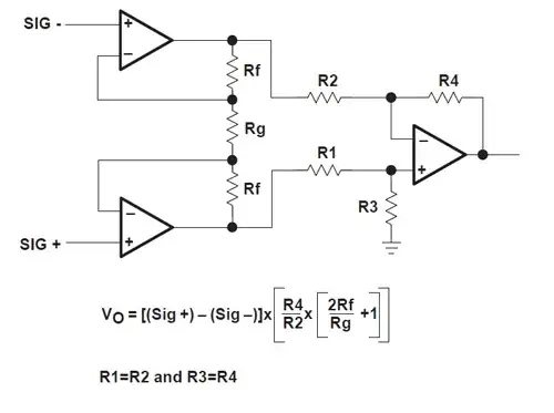
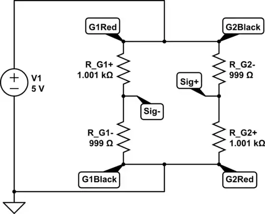
Schematic added by request: enter image description here

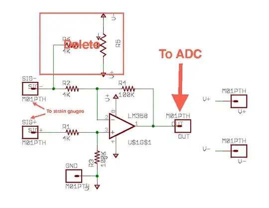
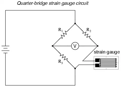
This is more-or-less the schematic for the circuit I built, but I put it together on a solderless breadboard so hopefully there wasn't too much field engineering in what I actually have working. The deleted part was an extra resistor and potentiometer that was supposed to be able to tune the strain gauge circuit so the output was exactly 0v with no load, but I ended up with a very slight positive voltage no matter what I did, and it wasn't significant so I didn't bother to debug it. Sig+/Sig- are where the strain gauges are wired to the amp circuit. I didn't build my strain gauge circuit, I used the scale, so I actually don't feel that knowledgable about the details of working with strain gauges, I just figured out how to use what was there. Mine had two pairs of gauges, and each pair had a V+, V- and signal wire. I wired the signal line from each pair to either Sig+ or Sig-, and then to power the gauges I wired the power from one pair and the ground from the other pair to V+ and the ground from one pair and power from the other pair to V-.

The resistor values in my circuit don't necessarily mean anything to you, because they were chosen to give the gain I need. Choose yours according to your needs.

Suboptimus
  • 871
  • 4
  • 6
  • The project you described is **exactly** the same as what I'm trying to build! The only difference is I'm measuring the changes in a [5lb coffee pot](http://www.amazon.com/Coffee-Pro-Vacuum-insulated-Airpot/dp/B004I2LTIS). I have a bathroom scale (with four, 3-wire load sensors) and now a kitchen scale with one, 4-wire sensor. I just can't figure out how to wire up this amplifier. Could you provide an (easy to follow) wiring diagram? – Andrew Aug 30 '11 at 21:29
  • You mentioned that you were able to get by with a single op-amp. I'm very interested to hear how you wired this up. The "In-Amps" seem to be too expensive for me for this project. – Andrew Aug 30 '11 at 23:14
  • Ok, I think I understand. You have four resistors and an op-amp? You mentioned that you chose the resistors based on the gain you needed. How would I adjust the values (which ones would I change) if I wanted the gain to be higher/lower? – Andrew Aug 31 '11 at 14:50
  • [Wikipedia's article on differential amplifiers](http://en.wikipedia.org/wiki/Operational_amplifier_applications#Differential_amplifier) has the equations for calculating the gain. I used the simplified case where R1 = R2 and Rf = Rg, so in my case 100K / 4K = gain of 25. – Suboptimus Aug 31 '11 at 22:35
  • Awesome! Thank you! That makes so much more sense! – Andrew Aug 31 '11 at 23:17
  • Very important is the "and then to power the gauges I wired the power from one pair and the ground from the other pair to V+ and the ground from one pair and power from the other pair to V-." -- This makes the gauges work in opposition to unbalance the bridge with increasing load. In the OP's diagram, the gauges would move in tandem with equal loads, moving both S+ and S- up and keeping the bridge in balance. – Dave X Nov 09 '15 at 20:25
  • The slight positive, no matter what you did was probably a slight manufacturing difference in the sensors. If you completely swapped sensor A for sensor B, you'd probably get the identical but negative offset. – Dave X Nov 09 '15 at 20:47
2

Note - I left the bottom part as another option as I didn't notice the package difference straight away.. edit still not quite sure how many opamps are available.

You may want to read up on (basic) opamp theory (which I have not gone into as it is explained better than I can in lots of places, and can/does fill books) before attempting any of this, as it's very easy for things to go wrong (even when you supposedly know what you are doing) They are not like some ICs that "just work", and the frequent source of much frustration for the new user of them.

The part you link to is a dual opamp (two opamps in one package) with no offest null or NC pins (see below for explanation of these) Here is the pinout from the datasheet:

enter image description here

You can do the single amp option below still, but since you have two opamps the two opamp version on page 4 of the TI app note is a better choice (works a bit better as it does not affect the input signal as much) The resistor values can be worked out with the equation, aim for a gain (the Vo part of the equation) of >100. Note that Steven goes into more detail about the downside of this option, and says it will not be "enough". I don't agree entirely - it's far from ideal, but it can be made to work if you adjust the gain to compensate for loading, as explained in the TI app note linked to above. However the result will be slightly non linear as impedance changes with input voltage at the inverting input. So if you have more than one opamp the instrumentation amplifier is the way to go.

Single opamp option

You need to make a differential amplifier, like this:

Wiki Differential opamp example

For your application, something like the values on page 3 of this application note would be appropriate. It is preferable to use something called an instrumentation amp for this, which uses 3 opamps, but you can make it work okay with one. The resistors set the gain of the opamp.

THe NC means "No Connect", so don't worry about that pin. The offset null is used to trim the very small offset (usually a mV or so) between the two inputs (ideally would have no offset)

Note - a very similar question was asked here a few days ago. The asker was using a 3 opamp instrumentation amplifier, but it should still be informative.

Oli Glaser
  • 54,990
  • 3
  • 76
  • 147
  • Sorry, the link to the amp is not the actual amp I am working with. I got mine from Radio Shack. – Andrew Aug 27 '11 at 15:55
  • @Andrew - this makes a big difference. We need to know the part number to be able to advise accurately, as there are many varieties of opamps with many different pinouts (e.g. 1,2,3,4 opamps per package, offset pins present/not present, pin 3 could be Vout on one part and +Vin on another) Some will not be particularly suitable for this application. What is the exact code printed on your opamp? – Oli Glaser Aug 27 '11 at 16:47
  • @Andrew - If you want to build the two-opamp instrumentation amplifier from the [appnote](http://www.ti.com/lit/an/sloa034/sloa034.pdf) Oli refers to, note that the amplification given in the appnote is wrong. Corrected equation [here](http://electronics.stackexchange.com/questions/18588/why-use-a-three-opamp-instrumentation-amplifier/18592#18592) – stevenvh Aug 27 '11 at 17:20
  • @Stephen - well spotted, is indeed. It relies on R1=2=3=4 being equal, but in the note it is given as R1=R2, and R3=R4. Including the R3 term allows for this though. – Oli Glaser Aug 27 '11 at 18:01
  • I have updated the link to the amp that I am actually working with. It's an LM741CN Op-Amp. – Andrew Aug 29 '11 at 18:51
  • Okay, it's a single opamp. It's not ideal but can probably be made to work - see suboptimus's answer, though the 741 probably won't be too happy with a very low supply voltage. If you have more than one use the instrumentation (2 or 3 opamps) configuration. Or you can simply buy a ready made instrumentation amp as stephen points out, probably the easiest option if you are new to all this. – Oli Glaser Aug 30 '11 at 11:38
  • 2
    LM741! Ugh. If you still have it in the package, I'd return it; 741s are like the Model T of op-amps -- they're 40+ years old, and they should be required to put a warning on the packaging. – Jason S Sep 02 '11 at 23:10
1

Try reversing the voltage to one of the two strain gauges. This has the effect of doubling the amount of voltage change. Wiring them the same generates ~ the same voltage at both amp inputs which equals zero differential.

Wayne
  • 11
  • 1
  • 2
    Can you explain a bit further on this, right now this seems more of a comment. – Kortuk Aug 22 '12 at 01:09
  • The sensors contain two strain gauges, one in tension and one in compression. Wiring both sensors in parallel, with equal loads, will change both the inverting and non inverting inputs by the same amount, rejecting the increased load as Common Mode noise. As specified, the circuit will measure the differences in loads on the two sensors. – Dave X Nov 09 '15 at 20:41
0

What Wayne said.

The sensors contain two strain gauges, one in tension and one in compression. Wiring both sensors in parallel, with equal loads, will change both the inverting and non inverting inputs by the same amount, rejecting the increased load as Common Mode noise. As drawn, @Andrew's circuit will measure the differences in loads on the two sensors, not the sum.

If you want the sum of the loads on both gauges, swap the excitation voltage on one of them like this:

enter image description here

Then, assuming a load changes the resistance of each of the 4 strain gauges by 1 ohm, the voltage across the center of the bridge is 4mv:

schematic

simulate this circuit – Schematic created using CircuitLab

Then, once you've got the increasing sum of the weights unbalancing the op-amp, configure the amplifier to amplify, as per the other answers.

Dave X
  • 372
  • 5
  • 12