2

How would one go about creating a library component for a through-hole fuse that sits in a holder? The part in question is this:

Fuse: http://www.digikey.com/product-detail/en/37202000411/WK4234BK-ND/245312 Fuse Holder: http://www.digikey.com/product-detail/en/56000001009/WK6235-ND/808503

I was thinking of going about it the way I go about DIP ICs that I need to be socketed, which is by adding the IC to the schematic, and simply putting "Socketed" in the comments/notes in the Bill of Materials. However, the above fuse/fuse holder is not standard (as far as I can tell), so I am wondering how others would go about this? Would it be acceptable to use the fuse in the schematic and in a comments/notes section of the BOM say "Socketed, Littlefuse P/N 56000001009" or something similar?

Just wondering if there is a standard way of doing this.

DerStrom8
  • 21,042
  • 8
  • 61
  • 95

3 Answers3

7

I would do it as with a socketed IC like you are describing.

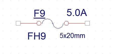
  • Fuse symbol to the schematic with a comment that its socketed.
    enter image description here
  • BoM for PCBA shows the socket for F7.
  • [optional] The actual fuse is in the BoM for top assembly (or some higher subassembly). Plugging in the fuse is a separate operation. It's also possible that slightly different versions of the product may have different fuses.
Nick Alexeev
  • 37,739
  • 17
  • 97
  • 230
  • This, which an annotation for socket and fuse part numbers. I've seen it cause confusion. – Matt Young Aug 17 '15 at 19:16
  • Great, that's what I was leaning towards (a combination of Option 1 and Option 2). I am using Altium, so I have added custom component parameters which I export to the BOM. I have one called "Notes", in which I will mention that it is socketed using the Littelfuse P/N, and tick the box making it visible on the schematic. Thanks very much! – DerStrom8 Aug 17 '15 at 19:21
3

I know this is old but just for keeping track of this, I decided to add my findings here.... I had a similar dilemma i.e. fuse holder and a fuse. You need both on the schematic and on the BOM so I found that the easiest way would be to create a symbol/partnumber for the fuse and a symbol/partnumber for the fuse holder. The fuse symbol would be created with no pins so as not to cause a problem within the capture tool. The two symbols would then overlap one another. See images. The end result would be that the fuse and fuse holder are on the BOM

fuse holder and fuse independent

fuseholder and fuse overlapping

1

Sorry I am late to the party and didn't see this earlier.

The crux of the matter is that people don't understand that the schematic for a PCB is often a cut-set or subset of the PCBA schematic and would have different drawing numbers, as the P/N for the PCB would be different from the P/N for the PCB assembly.

A fuse with a fuse holder or fuse clips is a case in point. On the PCBA schematic you would show both the fuse, with ref des of F#, and the fuse socket, with ref des of XF# or fuse clips with ref des of XF#A and XF#B. Thus your parts list (PL) is complete. F is the class letter for a fuse and X is the class letter for a socket, in this case a fuse holder. See IEEE 315 Clause 22.4 for official/standard list of class letters.

I would use the IEC 60617/IEEE 315A Clause 9.1.1 symbol (the one marked with IEC--it is a rectangle with a line running through it). Then on either end of the fuse I would show a female contact symbol per IEC 60617/IEEE 315A Clause 5.3.1 (the marked "Add: OR IEC"). If fuse clips then use ref des XF#A and XF#B. If a single fuse holder then use a mechanical linkage line connecting the two socket symbols and use the ref des XF#. For the PCB schematic you would copy over the PCBA schematic and delete the fuse as there is no land pattern/footprint for it and you won't get an error message when doing a DRC.

SamGibson
  • 17,231
  • 5
  • 37
  • 58