6

This TI application note shows this typical instrumentation amplifier (InAmp) with three op-amps (p.4):

3 opamp inamp

Further down the page the following two op-amp InAmp is shown:

2 op-amp inamp

The former is more common (I think) and easier to understand, but is there a good reason to prefer this one over the other? After all, it's more expensive since a third op-amp is needed.

Also, the two op-amp version doesn't have R3 or R4 in its \$V_{OUT}\$ equation. Is the amplification really independent of their value?

ocrdu
  • 8,705
  • 21
  • 30
  • 42
Federico Russo
  • 9,658
  • 17
  • 68
  • 117
  • R3 = R4 == unity gain. The value doesn't matter (within reason) – Majenko Aug 24 '11 at 13:09
  • @Matt - If it's only "within reason", that means that it *does* matter. And just looking at the schematic my common sense says it does, too. In my answer I have a corrected equation which has R3 in it. – stevenvh Aug 24 '11 at 15:30
  • @Matt - Besides, R3 = R4 doesn't imply unity gain. It's much more complicated than that, since RG + R1 are parallel to R4, and then there's R2 as well. – stevenvh Aug 24 '11 at 15:37
  • I guess TI is trying to make more money ;) – Frank Aug 25 '11 at 03:31

4 Answers4

5

The two op-amp design has in principle some drawbacks in comparison with the three op-amp design: the common mode input range is lower and the matching of the resistors is more critical if a high CMRR is to be achieved (Graeme, 1973). However, these drawbacks become less important at high values of overall gain

http://www.biosemi.com/publications/artikel7.htm

On the other hand, this claims the CMR is better for the two-op-amp version:

The two-op-amp configuration can provide higher CMR, especially in low-voltage, single-supply applications.

I'm not sure which is correct. Also:

The V1 signal must propagate through two op amps, but the V2 signal propagates through one op amp. When input signals contain frequencies greater than the flat portion of the op-amp gain curve (Reference 2), the V1 signal attenuates more than the V2 signal. The unequal attenuation causes the signal to unbalance, and CMR reduces at high frequencies.

http://www.edn.com/article/492092-Don_t_fall_in_love_with_one_type_of_instrumentation_amp.php#ref

endolith
  • 28,494
  • 23
  • 117
  • 181
  • I wanted to accept both stevenvh's and your answer, but yours had a few upvotes already. In stevenvh's answer I appreciate that he fixed the gain equation. – Federico Russo Aug 25 '11 at 08:06
2

Since R1 = R2, for the 2-opamp version the equation for \$V_{OUT}\$ simplifies to

\$V_{OUT} = \left( Sig_+ - Sig_- \right) \times \left( 2 + \dfrac{2 R2}{RG} \right) \$

and indeed there's no sign of R3 or R4. So I made the calculation again, and I found the following, different equation (I don't include the derivation because too much TeX involved):

\$V_{OUT} = \left( Sig_+ - Sig_- \right) \times \left( 2 + \dfrac{R1 + R3}{RG} \right) \$

which I like better because at least we have a term R3 here. Of course if \$R1 = R2 = R3 = R4\$ both equations are equivalent, but this condition isn't mentioned with the schematic. (I'd appreciate it if somebody can confirm that my equation is indeed correct.)

Madmanguruman noted that the gain is minimum 2 for this configuration, which also shows in the above equations. I'm not sure this is a serious restriction, since instrumentation amplifiers are usually used for much higher gains than 2, especially for strain gauge and other Wheatstone bridge measurements. Gains of 100 to 500 are common.
IMO Madmanguruman's other observation that \$Sig_-\$ passes through two opamps is not correct: the inverting input of the top opamp is kept at \$Sig_+\$, and \$Sig_-\$ only influences the currents through the resistors.

It looks like the 2-opamp version is a good alternative for the classic version in most applications, since, like you said, you save an opamp.

edit
In integrated form you don't gain (no pun intended) much from choosing a two-opamp version. The INA122 costs USD 6.86 while the three-opamp INA129 costs USD 7.35, both Digikey prices.

stevenvh
  • 145,145
  • 21
  • 455
  • 667
  • "influences the currents through the resistors" and "passes through two op-amps" are the same thing. – endolith Aug 24 '11 at 20:37
  • 2
    @endolith That's a better way of putting it, I think. There will be propogation differences in the two op-amp circuit vs. the three op-amp circuit from an input signal perspective. – Adam Lawrence Aug 25 '11 at 15:01
1

According to Wikipedia, the two op-amp circuit can only provide a gain greater than 2.

Also, you can see that for the two op-amp circuit, SIG- generates an 'intermediate' signal which is compared with SIG+ at another opamp, creating a small imbalance from a signal propagation perspective. The three op-amp circuit doen't have this issue, since each input has comparable propagation delays - each input generates an intermediate signal (with independent opamps) which get compared at a discrete differential amplifier stage.

R3 and R4 aren't in the equation because of \$R1 = R2\$ and \$R3 = R4\$, much like the first circuit where R1 and R3 aren't in the equation (again, because \$R1 = R2\$ and \$R3 = R4\$). The missing terms simplify out because of the equalities.

Adam Lawrence
  • 32,921
  • 3
  • 58
  • 110
  • What do you mean "because each input is essentially buffered"? Both designs have the same input impedance and first stages with gain. – endolith Aug 24 '11 at 20:39
  • 1
    Suppose that the output of an op amp is delayed a little bit from the input (as will nearly always be the case) and a high-frequency common-mode signal is present on the inputs. In the three-amplifier circuit, the two op amps at the left will delay the signal equally, so the two inputs of the output op amp will see the same delayed signal. In the two-amplifier circuit, one input of the output op amp will be delayed, but the other won't; the output amp will attempt to respond to this difference on the input, so some common-mode signal will leak through. – supercat Aug 24 '11 at 21:30
  • @endolith Not my best answer. I need to rethink how I stated things and try to improve. – Adam Lawrence Aug 25 '11 at 15:02
0

The challenge

It just so happened that while explaining the role of the common resistor Rgain in the input stage of the three op-amp instrumentation amplifier in a related question, I came here on this two op-amp circuit with a common gain-setting resistor Rg. Drawn in this perplexing manner, it appeared to me perfectly unfamiliar, and this caused me to try to discover what idea was hidden in it.

The common idea

Today, I thought about it almost all day and finally managed to see the general idea that connects the seemingly different circuit solutions of instrumentation amplifiers:

The input part of op-amp instrumentation amplifiers consists of two non-inverting amplifiers coupled by Rg.

The implementation

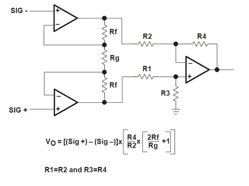
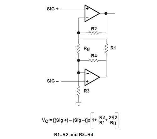
In the three op-amp circuit, the bottom resistors of the voltage dividers constituting the negative feedback network are connected by Rgain (Rg) "in series" while in the two op-amp circuit they are connected "in parallel" by Rg. Let's see what are these non-inverting amplifiers in the second circuit.

The bottom op-amp and resistors R3 and R4 form the first non-inverting amplifier. The top op-amp and resistors R1 and R2 form the second non-inverting amplifier. Their "following outputs" (the common points between dividers or op-amp inverting inputs) are coupled through Rg.

Operation

In the common mode, the two ends of Rg follow the input voltage variations of SEG- and SEG+ (figuratively speaking, they simultaneously "move"). So the voltage drop across and the current through Rg do not change. As though there is no resistor Rg connected between the voltage dividers (the name of this technique for artificial resistance increasing is "bootstrapping"). The two stages cooperate and the stage gain is minimum.

In the differential mode, one of Rg ends "freezes" or contrary "moves". Rg appears and connects in parallel to the divider's bottom resistor. The two non-inverting amplifiers counteract each other and the gain is high.

Circuit fantasist
  • 13,593
  • 1
  • 17
  • 48