0

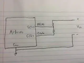
I need my Arduino to detect the state changes in a device - (ON or OFF).

In order do do this, I have to check the voltage between two points on the PCB of the device. When the device is OFF, the voltage between such points would be 0V; when the device is ON, the voltage between such points would be 7V. When the device is turned on, it stays on for at least 3-4 minutes.

The problem is the that Arduino can only take inputs up to 5V. I have thought about different options for taking down the voltage to 4-4.5V:

a.) use the old good voltage divider, with low resistor values for the purpose of drawing as little current as possible from the original device circuit. The easiest solution, but not the most efficient.

schematic

simulate this circuit – Schematic created using CircuitLab

b.) use a classic RC charge/discharge configuration. It's probably the most easy solution; however being the difference between the 7V input and 4-4.5V output very low, I think it may not work that expected.

c.) use a resistor in series with a capacitor - RC. By doing this I would i.) detect a voltage higher than 0 both when the capacitor is charging and when it is discharging; ii.) avoid drawing current from the device all the time when the device is ON, but only when it is being turned ON and OFF. In this case I would be keeping trace of the state of the device on the Arduino.

schematic

simulate this circuit

I think c. is the best option as it is both simple and energy efficient. Being the frequency of the circuit very low, the capacitor resistence is very high. This coupled with a 47kohm resistor draws very litte current. The RC time constant is 4.7 seconds. To me it sounds a good solution, but as it comes from the top of my head and have not seen it anywhere else, I suspect that might be missing something.

Would it be reliable? And would the addition of that affect the functioning of the original circuit of the device?

Please help me thanks.

geraldCelente
  • 153
  • 3
  • 12
  • You don't want to break the ground connection unless you have a very good reason for it. So you should swap top and bottom in your circuits. Your circuit with the capacitor will not work as intended as the cap will try to push / pull the voltage at Arduino side beyond the power rail (and the cap is way too large for this purpose to work safely). What do you mean by "not the most efficient" when using 157k voltage divider? The currents are pretty tiny. I don't know what "device" you are trying to connect to, but I could imagine that for safety reasons an opto coupler would be your best option. – jippie Aug 15 '15 at 17:46
  • Ok, thanks for the ground issue; I have now updated the circuit. By "not the most efficient" I mean that even though 157KOhm is a huge resistance, still a tiny current is being drawn as long as the device is on. With the c. option a current is only draw only for a few seconds when the device is turned on and off. Regarding the capacitor, what would be a good capacitance to reach this purpose? Would 4.7uF be fine? – geraldCelente Aug 15 '15 at 18:10
  • Possible typo in a). Did you want to say "*high* resistor values [to draw little current]" ? – Nick Alexeev Aug 16 '15 at 03:24

2 Answers2

3

The 7V signal will go right to the Arduino through the capacitor and will create overvoltage on the micro. When the signal goes down to 0, after the cap has charged, it will drive the input below 0V, another no-no.

A better way might be to use a MOSFET with the gate connected to the input.

schematic

simulate this circuit – Schematic created using CircuitLab

The circuit will typically draw well under 1uA from the 0-7V circuit. R2 is just there to allow the gate protection zeners in Q1 to kill any spikes that much exceed +/-10v.

Spehro Pefhany
  • 376,485
  • 21
  • 320
  • 842
2

The issue with option (c) is that you will expose the input to voltages beyond the rails +/- 7V. This could be addressed with a diode clamp circuit (probably already inside the micro) and a current limiting resistor. However, you will only get rising edges not falling edges.

I would use a simple resistor divider like in (a) however, I would keep the ground potentials the same (unless isolators are needed for some other purpose). Then, if power is an issue, connect the bottom of the divider to a GPIO on the arduino like this:

cir

To read:

  • Set the POLL pin up as an output
  • Read the MEAS pin to see the state of Vin
  • Set the POLL pin up as an input to reduce current draw in the divider

Make the resistor ratio such that the voltage at MEAS is nominally 5V. Make the sum of the resistors in the megaohms.

Note that this is only required if you are going for months to years of battery life.

Houston Fortney
  • 2,423
  • 1
  • 11
  • 14
  • 1
    Keep in mind that there will be current flowing through the top resistor to the top GPIO even when both are inputs because 7V > 5V + 0.6V. – Spehro Pefhany Aug 15 '15 at 19:48
  • 1
    That is an excellent point. You should probably combine my sampling approach with Spehro's circuit topology. – Houston Fortney Aug 15 '15 at 19:51
  • Yes, you could use Houston's idea and drive the pullup in my circuit with a port pin to reduce the average power consumption to near zero (assuming you care about the 5V supply power consumption). – Spehro Pefhany Aug 15 '15 at 19:53