0

I have a problem making a circuit like this working Taken from the link below

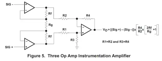
I got it from this TI application note. For testing purposes I have set:

\$R4=R2=R3=R1=47 \Omega\$

\$ Rf = 10 k\Omega\$

\$Rg= 26.70\Omega\$

The op amp \$V_S=+5V\$. This should give a gain of 750 having \$V_{SIG}\$ as 0.8E-4V/kg.

I agreed that 80kg would be enough for full scale. The problem is that this setup doesn't show any variations when i load the strain gauge. It just stays at 2.40V which doesn't make much sense since it doesn't reach near \$V_S\$. I am using the TL064. I have tried a lot and think my wiring is correct. Do you have any suggestions?

Update: I came up with the 750 of gain by assuming that:

\$R4=R2 <=> \dfrac{R4}{R2}=1\$
\$Gain=\dfrac{2Rf}{Rg}+1\$
\$(Sig_+)-(Sig_-) = V_{IN} => V_O=V_{IN} \times 1 \times Gain <=>\$
\$Gain = \dfrac{V_O}{V_{IN}} <=> \dfrac{2Rf}{Rg}+1 = \dfrac{V_O}{V_{IN}}.\$
\$V_{IN}/kg = 0.8E-4V/kg\$

I also i assumed that my absolute maximum load would be 80kg. So \$V_{IN(MAX)} = 0.8E-4 \times 80 = 6.4E-3\$ V

So we can determine the needed gain for

\$V_{OUT}=5V. G=\dfrac{V_{OUT}}{V_{IN}}=\dfrac{4.8}{6.4E-3}=750\$

Taking the previous equations: \$ \dfrac{2Rf}{Rg}+1 = 750 <=> 2Rf = 749 Rg <=> Rg = \dfrac{Rf}{374.5}\$

Knowing this and the resistors I had available I chose to set Rg as a function of Rf because i have to arrange the resistors(series or parallels to approximately get the desired gain) I chose:

Edit:
Corrected Equation mistake but still no results \$Rf=10 k\Omega => Rg = 10E3/374.5 = 26.70 \Omega\$ Considering I don't have this precise value I came up with \$Rg = 47 || 47 = 23.5\$ which is close to \$26.70 \Omega\$

Hope everything is clear for everybody, otherwise please ask for clarifications Thank you

stevenvh
  • 145,145
  • 21
  • 455
  • 667
Paulo Neves
  • 185
  • 2
  • 8
  • 3
    The TL064 is a low-power JFET op-amp. You're driving some very low resistances with R1 through R4 = \$ 47 \Omega \$. I would scale those values up by at least 100x (to \$ 4.7k \Omega \$) and see if anything changes. – Adam Lawrence Aug 22 '11 at 19:16
  • Why are you using an instrumentation amp? What kind of strain gauge? It generates a voltage? Are the voltages at SIG+ and SIG- between 0 and 5 V? – endolith Aug 22 '11 at 19:55
  • Yes the voltages at SIG+ and SIG- are 5V. The calculations i made were based on my expected full scale voltage through measurements of the voltage change by 1 kilo. I will update the questions so as to reflect the comments and the requests for clarifications. The circuit is composed of 4, 3 wire, strain gauges in full bridge(i think it is the correct term) – Paulo Neves Aug 22 '11 at 21:03
  • @aiwarrior: If SIG+ and SIG- are 5V, then you won't get any output. Do you mean that they are *between* 0 and 5 V? The strain gauges have an integrated amplifier that outputs 0 to 5 V signal? Why are you using an instrumentation amp? – endolith Aug 22 '11 at 21:17
  • Thanks for the clarification - 10e3/374.5 = 26.7, not 26.7e3. – Oli Glaser Aug 22 '11 at 22:27
  • I checked the equations twice and that escaped me hard. You were right regarding the gain. I will correct the circuit and report back to you. If it was that problem i will grant you the answer providing you remark it on your answer – Paulo Neves Aug 23 '11 at 00:15
  • 1
    @endolith - Strain Gauges are almost universally wheatstone bridges ( http://en.wikipedia.org/wiki/Wheatstone_bridge ). Basically the strain is reflected as the difference in two voltages, where both voltages are very high-impedance. It's pretty much what instrumentation amplifiers were invented for. – Connor Wolf Aug 23 '11 at 08:27
  • @aiwarrior - Why two 47\$\Omega\$ resistors in parallel? A simple 27\$\Omega\$ is also an E12 value and much closer. And if you place a (E24) 2400\$\Omega\$ parallel to it you get a gain of 749\$\times\$. BTW, 10000/374.5 = 26.70 – stevenvh Aug 23 '11 at 18:28
  • @stevenh - Thank you. I corrected the 26.70 value and its not that 27$\Omega is bad. Its just that i dont have a resistor with that value with me right now. – Paulo Neves Aug 23 '11 at 18:50
  • @aiwarrior - If you have a limited resistor range in stock [resistorcalc](http://www.avrfreaks.net/index.php?module=Freaks%20Tools&func=viewItem&item_id=1062) may be helpful. It calculates series and parallel resistors to get a specific value within the precision of your choice. Very handy. – stevenvh Aug 24 '11 at 06:16
  • @aiwarrior - I TeX-ified your question a bit more, just cosmetic changes. If you don't like them, rollback. – stevenvh Aug 24 '11 at 06:44
  • Thank you. I didnt know there existed such thing. I was actually going to make a small script to do that job. Thanks for the changes. Where are the guidelines for the TEX in question? – Paulo Neves Aug 24 '11 at 11:18

2 Answers2

1

You've made an error in the amplification.

\$G = \dfrac{2 \times R_F + R_G}{R_G}\$

With the values you're using this gives

\$G = \dfrac{2 \times 10k\Omega + 25.9k\Omega}{25.9k\Omega} = 1.77\$

If you want a \$G\$ of 750 you'll have to make \$R_G\$ = 26.7\$\Omega\$, so that

\$G = \dfrac{2 \times 10k\Omega + 26.7\Omega}{26.7\Omega} = 750\$

stevenvh
  • 145,145
  • 21
  • 455
  • 667
  • I had already made a comment saying i noticed that. And it didn't solve the problem. Sorry if i didnt edit it earlier to save you some time – Paulo Neves Aug 23 '11 at 10:44
0

I suspect your gain is too low - how do you get a gain of 750? I get a gain of ~1.7

Try replacing Rg with e.g, a 100 ohm resistor and see if that works a bit better. As mentioned, scale R1,2,3,4 up also - you could add some gain here too by making R3 and R4 larger.

I'm assuming you are using a wheatstone bridge?

EDIT - just saw your comment above. If the voltages at SIG+ and SIG- are both the same you will get no change. This is a differential amplifier, which means it amplifies the difference between the two inputs, not the inputs and ground. Can you confirm how you are connecting your strain gauge exactly? A schematic including the rest of the circuit would help greatly.

Oli Glaser
  • 54,990
  • 3
  • 76
  • 147
  • The voltages at SIG+ and SIG- are not the same. I even notice the change with the multimeter. It is just that it is really small. I don't have the schematic of the 3 wire gauge and i kind of only guessed through the pcb which kind of formed a bridge with the 4 Strain gauges having an excitation and signal terminals. I will prepare a schematic of how i think it works internally. The sensor is really similar to [this](http://www.sparkfun.com/products/10245) just the wires are of different colors. The circuit is really just 4 strain gauges of the 3 wire type in full bridge – Paulo Neves Aug 22 '11 at 23:23
  • Okay, try Rg 500, Rf 10k, R1/2 1k and R3/4 10k (or something similar - values don't have to be exact) Let us know how this performs. – Oli Glaser Aug 23 '11 at 00:14
  • I dont have 1k or 500 resistors with me and the closer i got is 680 Ohm. Can you explain your reasoning with the Gain of 410, so maybe i can adapt with the material i have at my disposal now? Thanks – Paulo Neves Aug 23 '11 at 00:59
  • My current reasoning is to just get it working - the exact gain is not important as long as it is high enough to see a change at the output. After you achieve this you can fine tune the gain. So I suggested a gain of >10 on the first stage, and >10 on the second, to give >100 overall - this should be more than enough to detect a change if the rest of the circuit is correct. 680 ohm Rg sounds okay, combined with the same values (or similar) – Oli Glaser Aug 23 '11 at 01:07
  • @aiwarrior: What are the actual voltages on SIG+ and SIG-? What is the difference? – endolith Aug 23 '11 at 14:03
  • @endolith: The minumum difference is 0.8mV and as stated 0.8*10^-4 V/kg – Paulo Neves Aug 23 '11 at 14:30
  • @aiwarrior - okay, we have confirmed there is a difference between the two, thanks. Please can you also confirm, what the voltage is from both SIG+ and SIG- to *ground*? This is important, it should be around 2.5V for both. – Oli Glaser Aug 23 '11 at 17:34
  • 2.58 on both SIgs to the ground. I am going to try to go through the wiring again to see if there is any problem – Paulo Neves Aug 23 '11 at 17:53
  • @aiwarrior - yes, check the wiring as thoroughly as possible, I am beginning to suspect this may be the problem now, as if set up as described it should work. Scale R1,2,3,4 up if you have not already. Make absolutely sure Rg is connected properly at both ends, I think (if it's not) this could cause the symptoms you are describing. – Oli Glaser Aug 23 '11 at 18:09
  • I rewired it and made sure that Rg is connected. I even changed amp IC to try for damage and the result at Vout-Ground is always fixed 2.40V. I will try and scale R1,..Rn to higher values so as to follow your advice even though i dont understand why, since it shouldnt affect the result and the thermal stability of lower resistors is bigger than higher values and the absolute error is also less. Thank you – Paulo Neves Aug 23 '11 at 18:59
  • @aiwarrior - Can you see any change on the output of the first two opamps when you apply pressure to the strain gauge? Do you have opamp V- going to 0V or -5V? If it's 0V you can try applying 2.5V to the bottom of R3 (though the symptoms you are seeing are confusing me a bit) Anyway, confirm whether there is a change of the first two opamps then we can proceed from there. – Oli Glaser Aug 23 '11 at 19:54
  • @OliGlaser let us [continue this discussion in chat](http://chat.stackexchange.com/rooms/1165/discussion-between-aiwarrior-and-oli-glaser) – Paulo Neves Aug 23 '11 at 20:20