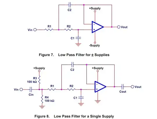
As JGord says, they are biasing circuitry. The second circuit takes the input through a series capacitor, which removes the DC component of the input level. Since the feedback path is also AC coupled through a cap, there's nothing reliably setting the DC input voltage of the op amp input, other than leakage through the input and the caps. That's why a resistive voltage divider has been added.
In the first circuit, the DC component of the input is provided by the source. Hopefully that is within the range of the op-amp centered on ground. In the second circuit, single supply operation requires that the center voltage be well above ground so AC coupling is pretty much required. Even if it weren't required for that reason though, it would still be useful in for example connectorized audio gear - with AC coupling and internal bias, the circuit takes care of itself without relying on the DC level of the unknown external input. (There is a possible cost though... for example, a sound card with such an input is great for audio, but can't be used for general purpose analog data logging since the bandwidth no longer extends all they way down DC)