1

I have power supply, analog part and microcontroller part on one 2-layer PCB board, very simple. The LCD is on the microcontroller part. It works normally when I have it on a separate board with only the microcontroller, but when I put it in this board, the LCD only displays black dots, not text.

I have tried a few times but it still gives me the same result. I was wondering whether my PCB has any problems? Is it a grounding or decoupling issue? Or something else? Please take a look at my PCB and give me some advice.

[enter image description here

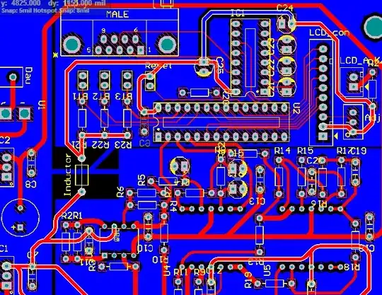
For more information, the power supply comes from a 7805 (on the Left Side of the Board). It drives a Cypress 27443 PSoC mcu, 1 INA126 Instrumentation Amplifier and 2 OPA4137 Op Amps. However I didn't put in the OPA when testing the LCD. The bottom part of the board is for the Amplifiers.

Passerby
  • 72,580
  • 7
  • 90
  • 202
vuquan
  • 19
  • 3
  • Need more information about the components, like what is the PSoC number, what is the application, what is OPA/7805 in the circuit etc... did you check the PCB track using a multi-meter for possible short circuit of LCD data lines etc. – Duresh Aug 03 '15 at 04:27
  • Thanks for your answer!I am using 27443 PSoC, the job of the uC is to convert ADC, provide DAC, reference voltage, some buttons and Rs-232 interface. The OPAs are used to process signal (in fact, it's a potentiostat circuit), they are on the lower side of the board, the left side is for power supply which I have separate grounds (don't know if that's properly grounded). I checked for the PCB track and they are fine, there are no short-traced – vuquan Aug 03 '15 at 04:34
  • What is the LCD that you are using? If it is Alphanumeric one, then your LCD wiring is wrong, else if you have an oscilloscope, check every data lines of the LCD for distorted pulses. – Duresh Aug 04 '15 at 02:06
  • Are your arrows pointing at curved traces (instead of 45°/mitred ones)? What makes that "bad practice?" See [here](http://electronics.stackexchange.com/questions/7913/why-is-there-such-a-strong-preference-for-45-degree-angles-in-pcb-routing) – Shamtam Aug 04 '15 at 02:40
  • Are you complaining about *curved traces*? Why? There are *so many* things that are much worse, like all the acute trace joins. Sidenote: The component you are asking about is /probably/ a negative voltage regulator. – Connor Wolf Aug 04 '15 at 02:40
  • Thanks for your answer, I am using LCD2004 (http://banlinhkien.vn/goods-1537-lcd2004-xanh-la.html), about the wiring, it's not wrong, the position of pins are not in order but I have wired them to a header and the wiring to LCD is free so I'm sure the problem doesn't lie in wiring. I'm more concerned about the distorted pulse you mentioned, could you explain it more clearly? About the traces, I am aware that 45° traces are mostly used and considered good, however I remembered reading somewhere that curved traces somehow are also good, so I decided to give it a try. – vuquan Aug 04 '15 at 03:33
  • @ConnorWolf Yes, that's a negative voltage regulator. I want to ask a favor, could you list some bad things in my PCB and tell me how to correct them, I have read many notes and documents about pcb design but I didn't seem to understand them thoroughly and put them in practice – vuquan Aug 04 '15 at 03:39
  • If you are directly plugging the LCD to the connector that has the label "LCD_con", then the LCD is not going to work. Because I assume that you are using 4-bit interface rather than 8-bit interface. Then you should communicate with the LCD using the last 4-bit not the first 4-bits (http://www.electroons.com/electroons/images/lcd.bmp). And also I hope you are not using external Vref pins for analog? – Duresh Aug 04 '15 at 05:15
  • @Shamtam, Thanks a lot for the info, I will correct my answer. – Duresh Aug 04 '15 at 05:40
  • This does not provide an answer to the question. To critique or request clarification from an author, leave a comment below their post - you can always comment on your own posts, and once you have sufficient [reputation](http://electronics.stackexchange.com/help/whats-reputation) you will be able to [comment on any post](http://electronics.stackexchange.com/help/privileges/comment). – PeterJ Aug 04 '15 at 07:19
  • I am doing exactly the same as the picture you posted (http://img.webme.com/pic/p/psocolombia/2c.jpg - this picture is from the datasheet of LCD UM in PSoC). The problem here is that when I build a separate board with only digital components: uC, buttons, LCD,... (the analog signal goes to analog board via header), the LCD works fine but when I put all of them together as in the question, the LCD doesn't work anymore. And what do you mean by "using external Vref pins for analog"? As you can see on the board, there are three signal lines, they are ADC, DAC and Ref(2.5V), does that count? – vuquan Aug 04 '15 at 07:39

0 Answers0