If someone can explain why a capacitor blocks DC, but not AC, with some math, I will understand all of that much better. I know that there are picture animations illustrating this, but I really want to know this a little bit more detailed.
Asked
Active
Viewed 4.0k times
27
-
1you won't find better than this to explain the concept https://www.youtube.com/watch?v=NInt1Ss3vQ4 – Sabir Moglad Jul 29 '15 at 09:25
-
1Maybe looks silly but I see as transfer of energy with a string with 2 nodes, if one part shake the other will shake. no shake no transfer. – emirjonb Jul 29 '15 at 09:58
-
How about this : http://www.funtoosh.com/f_images/engineering_ac_dc.jpg :) – TJ- Jul 30 '15 at 09:33
-
consider a liquid, driven by a force like gravity. DC means the gravity always pull in the same direction, AC means it changes. A capacitor is a wall in the middle of the tube where your flux moves. In DC, you can see that basically nothing happens as soon as a the liquid is stable. In AC, the halves of the liquid remain on their respective sides of the wall, but they still move back and forth. – njzk2 Jul 30 '15 at 23:49
8 Answers
44
Conceptual answer: Capacitors are essentially two plates that are mounted next to each other, with a gap between them so that the plates don't touch. That's why it's drawn as --| |-- on a diagram.
Direct current can't jump the gap between plates, because it would take a massive amount of voltage to force the electron to jump the gap between plates. The electrons hit the plate and stop.
Alternating current, on the other hand, is moving the electrons back and forth in place -- so the plate on one side of the capacitor is constantly having electrons pushed in and then pulled back out. This motion creates a small electric field which induces the same alternating current in the other plate, because electric fields can jump the gap between plates.
Hope that helps with your general understanding. Other people have posted lots of great math, but I didn't see much in the way of conceptual understanding of the physics at play.
m.Alin
- 10,638
- 19
- 62
- 89
David Wilson
- 544
- 4
- 4
-
This is what my answer was going to be. I would add something about the electric fields in both the AC and DC cases for completeness. – Matt Young Jul 29 '15 at 14:43
-
OP asked "Please if someone can explain it with some math" - where is the math? :) Good answer though. – Rev Jul 30 '15 at 06:31
-
@MattYoung can you explain the dc electric field concept to me? – muhammad muheeb Jul 30 '15 at 19:35
-
19
Seems like the intuitive answers aren't doing it for you, so let's go through the math.
A capacitor consists of two conductors separated by an insulator such as vacuum, air, or a dielectric (insulator). When you put a voltage across the gap, one conductor develops an excess positive charge while the other develops an equal and opposite excess negative charge. The equation for this is \$Q = CV\$, where \$Q\$ is the excess charge and \$V\$ is the voltage. The ratio of the two is called the capacitance (\$C\$), and is determined by the geometry of the conductors and the properties of the insulator.
In circuit theory, we usually work with current, not charge. So you'll usually see another equation for capacitors:
$$i = C \frac {dv}{dt}$$
Let's see how this works in a simple RC circuit.
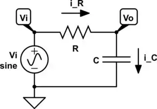
simulate this circuit – Schematic created using CircuitLab
We can use Ohm's law and the capacitor equation to create a KCL equation for the \$v_o\$ node.
$$i_R = i_C$$ $$\frac {v_i - v_o} {R} = C \frac {dv_o}{dt}$$ $$RC \frac {dv_o} {dt} + v_o = v_i$$
\$v_i\$ and \$v_o\$ are both functions of \$t\$. This is a linear first-order differential equation. How easy it is to solve depends on \$v_i\$. The simplest situation is where \$v_i\$ is constant:
$$RC \frac {dv_o}{dt} = v_i - v_o$$ $$\int{\frac {dv_o} {v_i - v_o}} = \int \frac {1} {RC} dt$$ $$-\ln (v_i - v_o) = \frac t {RC} + C_0$$ $$v_i - v_o = e^{-t/RC}e^{-C_0}$$
\$C_0\$ is a constant of integration. For simplicity, we'll give \$e^{-C_0}\$ the name \$C_1\$:
$$v_i - v_o = C_1e^{-t/RC}$$
We need an initial condition to solve for \$C_1\$. This condition is the value of \$v_i - v_o\$ at \$t = 0\$. If the capacitor is discharged, \$v_o(t=0) = 0\$ and \$C_1 = v_i\$, which gives exponential decay:
$$v_o = v_i - v_ie^{-t/RC}$$ $$v_o = v_i(1 - e^{-t/RC})$$
If the capacitor is charged, \$v_o(t=0) = v_i\$ and \$C_1 = 0\$, which gives us the DC condition:
$$v_o = v_i - 0 \cdot e^{-t/RC} = v_i$$
So at DC, the capacitor acts like an open circuit. But what counts as DC? No voltage is really constant for all time. Many aren't even constant for five minutes! The time constant \$RC\$ tells us how long we have to wait before the capacitor voltage is stable enough for our needs. Let's say we flip a switch and connect a DC voltage to an uncharged capacitor through a resistor. How long does the capacitor voltage to settle to within 0.1% of its final value?
$$v_o = 0.999v_i = v_i(1 - e^{-t/RC})$$ $$e^{-t/RC} = 0.001$$ $$t = -RC \ln 0.001$$
If \$R = 10\ k\Omega\$ and \$C = 1\ \mu F\$, the answer is 69 milliseconds.
Now that we have a practical definition for DC, let's look at AC. We're only going to consider sinusoids here, since you can use Fourier transforms to express any signal in terms of sinusoids. Back to our differential equation:
$$RC\frac {dv_o} {dt} + v_o = V_i \cos (\omega t)$$
There is some nasty trig here that I'm not going to go through. I'll give you the short version instead. Based on the form of the differential equation, you assume that \$v_o\$ must be something like:
$$v_o = A \cos (\omega t) + B \sin (\omega t)$$
Then, after a lot more work, you discover that the final answer is:
$$v_o = \frac {V_i} {\sqrt {1 + (\omega R C)^2}} \cos (\omega t - \tan^{-1} (\omega RC))$$
Note that the amplitude of the capacitor voltage depends on the frequency as well as the RC time constant! This is because we're taking derivatives of sinusoids, and the derivatives of sinusoids are proportional to their frequency:
$$\frac {d}{dt} A \cos (\omega t + \phi) = A \omega \cos (\omega t + \phi)$$
Also note that this voltage has the same frequency as the input voltage, but a different amplitude and phase.
Solving differential equations like this is difficult and time-consuming. Fortunately, there's an easier way -- phasor analysis. Instead of using real-valued sines and cosines, we use complex exponentials like \$e^{j \omega t}\$. These make the differential equations much simpler, allowing the frequency (which is always the same) to drop out altogether, leaving us with only amplitudes and phases. We can combine those into single complex values.
$$v_c = V_C e^{j \omega t}$$ $$i_c = I_C e^{j \omega t + \phi} = I_C e^{j \omega t} e^\phi$$ $$i_C = C \frac {dv_c}{dt}$$ $$I_C e^{j \omega t} e^\phi = C \frac {d}{dt} V_C e^{j \omega t}$$ $$I_C e^{j \omega t} e^\phi = j \omega C V_C e^{j \omega t}$$ $$I_C e^\phi = j \omega C V_C$$ $$\frac {V_C} {I_C} e^{-\phi} = \frac 1 {j \omega C}$$
$$Z_C = \frac 1 {j \omega C}$$
This "impedance" acts like a complex-valued resistance, and follows a rule similar to Ohm's Law. As you can see, it too is dependent on the angular frequency \$\omega\$. The ratio of current to voltage is large when the frequency is large and small when the frequency is small. At the extremes we say that a capacitor acts like an open circuit at DC and a short circuit at high frequencies. This means that at DC, you can put a large voltage across a capacitor without current flowing through it. At high frequencies, you can run a large current through a capacitor without seeing a voltage across it.
I hope this mammoth answer clarified some things. Please feel free to ask follow-up questions if there's anything you don't understand.
Adam Haun
- 21,331
- 4
- 50
- 91
-
1Since OP explicitly asked about "Please if someone can explain it with some math" this certainly deserves a +1. – Rev Jul 30 '15 at 06:30
14
We know the reactance, \$X_C\$, of a capacitor is given by:
$$ X_C = \frac{1}{2\pi f C} $$
And we know the frequency of DC is 0 (Zero). If we solve the above equation we will get \$X_C = \infty\$, which means very high value of resistance so the capacitor blocks DC.
For AC signal there will be a known value of frequency and will have some finite reactance, known value of impedance.
This the reason why capacitor blocks DC not AC.
Sanjeev Kumar
- 1,474
- 11
- 19
-
3"**We know** the frequency of DC is 0(zero)" No **we** don't. Where is your proof of this crucial statement? (http://electronics.stackexchange.com/questions/41915/is-frequency-for-dc-is-zero) (http://www.quora.com/Does-direct-current-have-a-frequency-If-it-does-how-can-it-do-so-if-its-not-alternating-between-negatives-and-positives) Are dielectrics perfect insulators? (http://swissenschaft.ch/tesla/content/T_Library/L_Theory/EM%20Field%20Research/A%20capacitor%20with%20resistivity.pdf) If not, how does this affect the formula you have used. – JIm Dearden Jul 29 '15 at 10:55
-
Plz refer wikipedia https://en.wikipedia.org/wiki/Direct_current Various definition section – Sanjeev Kumar Jul 29 '15 at 11:37
-
1Or just try to type "frequency of dc" in google, on top of the window will get the definition with frequency – Sanjeev Kumar Jul 29 '15 at 11:45
-
4For DC to have zero frequency it has to be supplied for an **infinite time** - as soon as you switch a circuit ON and OFF you introduce a time dependant component. This applies to this question - if the capacitor is totally discharged and you switch the circuit ON you get an initial current (V/R) - this continues to decay exponentially until you switch OFF. At NO TIME do you actually get a ZERO CURRENT i.e it does not BLOCK the DC as you would with a perfect insulator. Added to that the dielectric also conducts (a very small but finite current). – JIm Dearden Jul 29 '15 at 12:00
-
You itself accepting that DC has a zero frequency, your first line comment "For DC to have zero frequency it has to be supplied for an infinite time" same thing you cant say for AC in any of the cases. – Sanjeev Kumar Jul 29 '15 at 12:29
-
No I don't accept DC has zero frequency and I deliberately put **infinite time** in bold to show that it can't. The universe is just over 13 billion years old - that's still not infinite time. Any practical DC source we use today (battery, psu etc.) is switched on and off. Any practical (real world) capacitor we make and use leaks because the dielectric is not a perfect insulator therefore no real world capacitor can ever truely 'block' a DC source (uni directional current). We **approximate** by ignoring the small current that flows and not taking into account the effect of time. – JIm Dearden Jul 29 '15 at 14:08
-
4@JImDearden, I think your definition of DC is flawed (and the links you posted don't really prove your point either and the first one actually says the opposite). If I have a signal that begins instantly and lasts at a constant voltage for a period of time and ends instantly, I have a DC voltage. Period. Infinite time not required. Please direct us to an academic journal article or textbook that corroborates your claim. – Mr. Mascaro Jul 29 '15 at 14:16
-
@Mr.Mascaro - Your DC had to be switched ON at some point in time, eventually it will either be switched OFF or its energy source will eventually run out - let's say it takes T seconds (even if T is several million seconds). Therefore it is actually a **pulse** not continuous DC. If you apply Fourier analysis (time to frequency domain, non periodic pulse) the funadamental frequency is 1/T. Now this may be a very low frequency and as such any capacitor will have an extremely high reactance to that frequency. Its only when T is infinite that F is zero. – JIm Dearden Jul 29 '15 at 14:46
-
8@Mr.Mascaro Jim's definition of DC is technically correct, but pedantic. It's a theory vs. practice trade off, much like how a capacitor never really stops charging, but after 5 time constants, we say "close enough". For DC to truly have no spectral content other than zero, it much be constant from negative to positive infinity. – Matt Young Jul 29 '15 at 14:47
-
1@MattYoung, that's only if you use an infinite frame of reference. The question did not refer to any such frame and the response is therefore incorrect. If you change the frame of reference to a discrete period, you can have DC within that window with no changes to any equations or theory. – Mr. Mascaro Jul 29 '15 at 14:51
-
@Mr.Mascaro The question doesn't mention the time domain at all, and I have better things to do than argue over the definition of DC in a chain of comments. – Matt Young Jul 29 '15 at 14:58
-
2This is absolutely not *"the reason"* that a capacitor blocks AC. This is simply a mathematical *description* of a capacitor's impedance. Capacitors don't behave they way they do *because* some equation tells them to. This is an awful, dogmatic answer to a question with an otherwise very real, physical answer. You derive this equation *from* the capacitor's behaviour and the properties of the physical system it represents, not the other way around. – J... Jul 29 '15 at 16:59
-
After reading all those comments (especially from J...), I really don't know how to vote this answer :o – Rev Jul 30 '15 at 06:37
-
Just noticed a typo... I should have said `...that a capacitor blocks DC`. Anyway, I primarily object to this sort of answer because it promotes the sort of thinking that science and engineering are a book of rules that we should simply take for granted - that we should answer *"why"* questions by pointing to the rules and saying *"because"*, completely ignoring how those rules came to be. These equations derive from an understanding and analysis of the physical system they describe - to substitute them for that understanding does a terrible injustice to a student, imo. – J... Jul 30 '15 at 11:48
8
The current through a capacitor is proportional to the change in voltage across the capacitor \$\Big(\dfrac{dV}{dt}\Big)\$. Thus, \$i=C \dfrac{dV}{dt}\$. Thus, if \$\dfrac{dV}{dt}\$ is zero, which is the case, by definition, at DC, the current is zero.
Ricardo
- 6,134
- 19
- 52
- 85
Scott Seidman
- 29,274
- 4
- 44
- 109
7
Looking at the physics is probably easiest. A capacitor is basically an isolator sandwiched by metal plates. You may think that an isolator would block all current, and that definitely explains the DC behavior.
With AC, however, the electrons that flow into the negative side cannot jump to the other side. However, that other metal plate does have quite a few electrons of its own, and those are repelled by the new electrons. Those electrons leave on the other side. But you now have an electric field over the insulator.
This situation cannot increase forever. You can't keep pushing more and more electrons on the negative plate, and also there aren't enough electrons left to repel from the positive side. But with AC, the flow of electrons reverses periodically. All those electrons squeezed on the negative side will rush out, and the electrons that were previously repelled will rush back to the positive side. Halfway through the cycle, both metal sides are electrically neutral, and in the second half-cycle the electrons now flow to what previously was the positive side.
In effect, the insulator allows only a limited number of electrons to flow into the negative side condensator, but with AC those electrons will flow back out in the other half of each cycle.
MSalters
- 561
- 3
- 7
5
Imagine a spring which is
pressed steadily. At some very short time after starting, you cannot push any further, so it stays where it is. This is what DC does with a capacitor.
periodically pressed and released. This works very well and is what AC does.
-
Not a good analogy. You do not need a saturating nonlinearity to describe a capacitor. – Scott Seidman Jul 30 '15 at 12:12
-
@ScottSeidman Maybe it is not the best analogy, but it can be helpful to a lay to understand it. – glglgl Jul 31 '15 at 05:34
1
For a capacitor the charge is directly proportional to the applied voltage. Q=CV In case of DC the voltage is constant,giving a charge that is constant with time.Since current is described as the time derivative of charge,therefore DC cannot flow through the capacitor.In case of AC,charge is time varying so AC flows through the capacitor.
muhammad muheeb
- 175
- 2
- 12
0
No, the capacitor does not block the DC.
The most general form of capacitor charging equation is
$$ v_c(t) = V_s + \left[ v_c(t_0) - V_s \right] e^{-\dfrac{t-t_0}{RC}}, \quad t\ge t_0. $$
Where, \$V_s\$ is the DC supply voltage, \$R\$ is the charging resistor or the input resistance of the system coupled, \$C\$ is the capacitor capacitance, and \$v_c(t)\$ is the voltage on the capacitor.
This equation tells us that a capacitor needs infinite time to charge up to the supplied DC voltage. This "infinite time" is a time period which is longer than the life time of our universe. Which implies that a capacitor cannot completely and theoretically block DC voltage in the environment of our universe.
hkBattousai
- 13,913
- 31
- 114
- 190