Most piezos I've seen have just two connections, but this type has three.
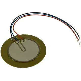
What's the third wire for?
Asked
Active
Viewed 5.4k times
53
Federico Russo
- 9,658
- 17
- 68
- 117
-
2I accepted stevenvh's answer because it makes it clear to me. Don't let this stop you from posting other answers, however, possibly giving more detail. I might change my mind :-) – Federico Russo Aug 14 '11 at 14:10
-
It's a good answer. Nice and clear and to the point. – Russell McMahon Aug 15 '11 at 08:03
2 Answers
58
They're called self drive types, and they're meant to be used as part of the oscillator:
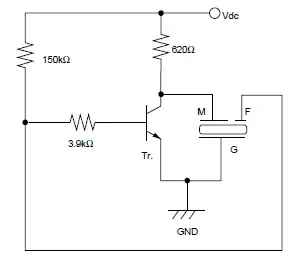
The piezo effect works both ways: if you apply a voltage the piezo stretches, but also if it stretches it creates a voltage. This principle is used to create a feedback signal which drives the oscillator.
The advantage of the self drive is that it will automagically work at its resonance frequency, where it produces the loudest sound. In 2-wire circuits the oscillator's frequency is independent of the piezo's resonance frequency, and it's the designer who has to make that they're close.
For the piezo of your picture:
"G" = black
"M" = red
"F" = blue
(I guess M, F and G stand for Main, Feedback and Ground, resp. CMIIW)
stevenvh
- 145,145
- 21
- 455
- 667
-
8I found a 3 pin piezo puzzer in a smoke detector and was wondering how it works (and why it's there). Now that you say it allows to produce the loudest sound, it makes sense... – tigrou May 02 '15 at 16:18
-
Since the device optimizes its own sound and driving frequency, this also means you can lower the sound frequency by increasing the mass of the driver, perhaps by attaching a small weight (a bb) to the back of the device, the brass side. This might also make it more efficient. – MicroservicesOnDDD Mar 31 '21 at 19:36
9
Here is a good in-depth explanation of buzzers including self-driven ones + some usefull schematics: Piezoelectric Sound Components Application Manual (812kb).
Excerpt (from p.5):
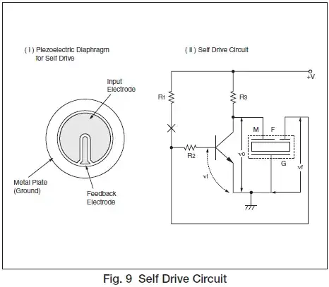
Self Drive
Method Fig. 9 shows a typical application of the self drive method. The piezoelectric diaphragm provided with feedback electrode shown in Fig. 9 (i) is involved in the closed loop of a Hartley types oscillation circuit. When the frequency is closed to the resonant frequency, the circuit satisfies oscillating conditions, and the piezoelectric diaphragm is driven with the oscillating frequency. Fig. 9 (ii) shows a simple oscillating circuit consisting of one transistor and three resistors. In general, the node support shown in Fig. 3 (a) is popular in the self drive method. Proper resonance of the piezoelectric diaphragm by the node support provides stable oscillation with high mechanical Qm of vibration but also a single high pressure tone.
-
1I agree, it does, but linking to a pdf with all the information makes for a bad answer. Please include some of the relevant information in your answer text. – Passerby Mar 23 '14 at 19:36
-
1@hurufu Welcome to EE.SE. There is a slight problem with answers, which primarily consists of link to an external page (so called *link-only answer*). If that page moves in the future, then the link dies, and the answer becomes largely useless. So, include an abstract (or excerpt, or synopsis) along with the link. – Nick Alexeev Mar 23 '14 at 19:44
-