The "gate" you've shown is confusing I think because while its purpose may be to have LED2 and LED1 give opposite indications, the input to the "gate" is a current and the output is a voltage. In most cases, it makes more sense to define logic gate behavior for both inputs and outputs in terms of voltage. For example:
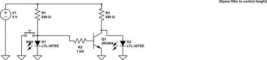
simulate this circuit – Schematic created using CircuitLab
In this example, a logic high is a signal which will sit at least 1.5 volts above ground if no more than 5mA is drawn from it; a logic low is a signal below 0.6 volts. The left circuit will output a voltage of at least 1.5 volts until the current drawn from it exceeds 5.1mA. The gate in the middle (starting before the 1k resistor) draws slightly under 1mA if the input is at 1.5 volts); one could attach four more similar gates without exceeding the 5mA limit of the source (though any current used to feed gates will reduce the LED brightness). If the input is over 1.5 volts, the base-emitter current will be at least 0.8mA, and the transistor should have no trouble sinking the 6.4mA necessary to pull its collector down to 0.6 volts. If the input is below 0.6 volts, then R3 should have no trouble pulling the output up above 1.5 volts if nothing downstream demands more than 5mA.
Note that all LEDs are referenced to ground. If one is willing to have a buttons and LEDs which are floating, one can build an "inverter" without needing any transistors, but incorporating such a device into a larger circuit will be difficult. Assuming LEDs want roughly 10mA at about 1.8 volts:
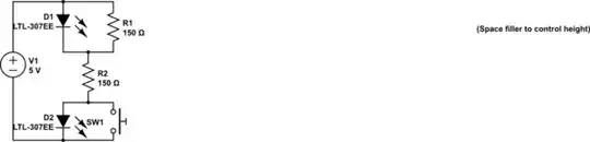
simulate this circuit
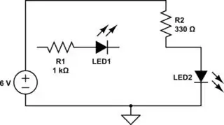
When the switch is open, D2 will drop 1.8V; the 3.2 volts remaining will be divided between R1 and R2, with each dropping 1.6 volts at 10.6mA, so D2 will get 10.6mA. When the switch is closed, D1 will drop 1.8V. R2 will drop 3.2 volts at 21.3mA, and R1 will drop 1.8 volts at 1.2mA, leaving about 9.3mA for the D1.