0

I'm trying to use a N-channel mosfet as a switch for controlling a LED, but the most of the voltage is dropped in the mosfet itself (drain-source) and the led are not turning ON. The voltage in the gate is 3.3[V] and in the drain is 4.2[V]. What is my problem? I've seen this circuit before for controlling LED's and it works, Should I use a P-channel instead? The circuit is already done, so I measure the voltages on my board.

Attached is a screenshot of the circuit.

Thanks!

Circuit

3 Answers3

2

Let's analyze this. Assuming the MOSFET is conducting and the LED is getting, say, 10mA with voltage drop of around 1.5V, the voltage on the Source pin will be 1.5V+220*10mA = 3.7V. While the gate voltage is 3.3V. So your Vgs is -0.4V. Which, of course, will never make the MOSFET conducting. Contradiction. To overcome this you need to make sure Vgs is sufficient by making it known and constant by connecting source to the ground and moving the load (resistor and LED) in series with the drain.

Eugene Sh.
  • 9,986
  • 2
  • 26
  • 41
2

For a hobby circuit you could probably get away with using BSS314PE P-channel MOSFETs. It will pass only a few uA when the gate is at 3.3V and will turn on fairly well when the gates are low. If the few uA are visible, a 10K resistor across the LED will keep it off.

It's not a good way to do it- better to level-shift and use a p-channel MOSFET with gate driven from 4.2V to 0, but that's considerably more complex.

Or use n-channel logic-level MOSFETs and shunt the current away from the LEDs (and waste the power).

The problem with the circuit you have is that you can only get the input drive voltage minus Vgs(on) at the source, which will probably end up being a couple of volts. It would be better if you put the transistors on the other side of the resistors, but still probably not good enough.

Spehro Pefhany
  • 376,485
  • 21
  • 320
  • 842
2

You are currently using a N-channel MOSFET as a high-side switch. Although this is possible, the more common configurations (i.e. easier to drive) are P-channel high-side switches and N-channel low-side switches. This question discusses the four possible topologies so I won't repeat that here.

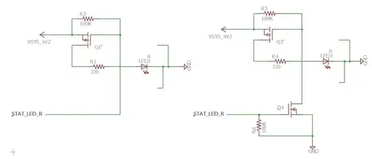
I have redrawn your circuit using a P-channel MOSFET as a high-side switch.
enter image description here

When the gate to Q1 is grounded, the MOSFET will be on, and so will the LED. When the gate is high, then the MOSFET and LED will be off. So the logic is inverted as far as the STAT_LED_R line goes; a 0 turns on the LED, and a 1 turns it off.

You indicate the gate voltage you are using is 3.3V. Because R1 provides the necessary high voltage (4.2V) for the gate drive, then if the output pin is 5V tolerant, you can use an open-drain configuration for the pin and connect the gate of Q1 directly to the STAT_LED_R line.

If the output line is not 5V tolerant, then you will need to add a second N-channel MOSFET (Q4) to switch ground to the Q3 gate as shown on the right side. In this case, the logic is not inverted; a 1 on the output will turn on the LED.
tcrosley
  • 47,708
  • 5
  • 97
  • 161