Why didn't you follow the suggestions from this answer?
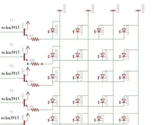
You have places your LEDs in parallel, which is a Bad Habit™. Each LED should have its own series resistor.
You also placed the LEDs in reverse, which may be caused by your placing of the GND on top of the schematic; if you would place it at the bottom, where it's usually placed, you might notice the error easier.
The datasheet doesn't say in so many words, but I presume that the outputs of the comparators are open collector NPNs. That means that to turn on LED the NPN will sink current, when the LED is off it's just open, i.e. there's no current. Your NPN transistors are in common collector. This could work if the LM3915's output would source current, but I wonder if you meant it that way. It would mean that the LEDs' function is reversed: a LED which would be on in the typical LM3915 application would be off, and vice versa. Did you mean to use PNPs? If so you have to add a base resistor (like I mentioned in the other answer).
edit
I'll repeat the schematic from the other answer:
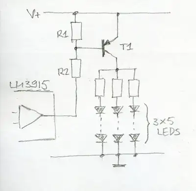
Since you only seem to have +5V you won't be able to place more than 1 LED in series: at 2.2V forward voltage 2 LEDs would leave too little voltage drop for the transistor + resistor. But you still have to use a resistor per "string"!
Maybe I wasn't clear enough about the type of transistor, but you're using an NPN, whereas my solution has a PNP. The difference in the symbol is in the direction of the arrow: for an NPN it points to the emitter, for a PNP it points from the emitter to the base. See also this question.
Also in the other answer I explained the function of R1 and R2. I don't know why you have omitted them.
edit
A PNP transistor will allow a higher current from emitter (the arrow's tail) to collector if a small current flows from emitter to base (following the arrow). R2 allows this base current if the LM3915 makes its output low. If you choose a 4k7 (that's shorthand for 4700\$\Omega\$, see also this question), you'll have about 1mA flowing from the base. The collector current is the base current multiplied by \$H_{FE}\$, a value you find in the transistor's datasheet. For the BC557 this is minimum 125, so we can have at least 125mA collector current. Can have, because we'll limit it to a lower value with the LEDs' series resistors. That's not only to protect the LEDs, but also the transistor doesn't allow more than 100mA collector current. That's why I advised for more than 4 LEDs (4 x 20mA = 80mA) to use a second transistor.
R1 is needed to make sure that the transistor won't conduct if the LM3915's output is off; there may be some leakage current.
On second thought the BC557 is not such a good choice. It's a small signal transistor, and we need more of a switching transistor, capable of a higher current. The current of the BC557 is also limited by its \$V_{CE(SAT)}\$, the voltage over the transistor when it's completely on. For the BC557 this can be nearly 1V, and a 1A current would cause a 1W dissipation, which is too much. We need a transistor with a lower \$V_{CE(SAT)}\$. Let's have a look at the NSS30070MR6T1G. This can source 700mA, more than enough to feed 20 LEDs in parallel at 20mA, and it still has an \$H_{FE}\$ of 150. Yet that means we need a bit more base current, so let's make R2 = 1k, that will give us at least 4mA base current.
afterthought:
In a comment you mentioned 20 LEDs per output. Does that mean that the bases of four of the transistors are connected to the same output of the LM3915? In that case provide a separate R1 and R2 for each transistor, and connect the lower end of the R2s together to the LM3915's output.
Note that you'll need a lot of current: 10 outputs x 20 LEDs per output x 20mA per LED = 4A (20W at 5V). If you could use a higher supply voltage like the 12V I used in my example you could place each time 4 LEDs in series and only require 10 x 5 x 20mA = 1A (12W at 12V). Note that you need much less power here. That's because of the voltage drop over your resistor. In the 5V version you lose 5V - 2.2V = 2.8V, representing 56% of your power in the resistor. In the 12V version you lose only 12V - (4 * 2.2V) = 3.2V or 27% of your power.