8

I have a board with a 50 Ω impedance controlled track. I have got the boards manufactured. The manufacturer has sent me 2 additional boards viz - test coupons. I understand that test coupons have the same impedance controlled design and are used by developers to test the impedance controlled track.

  • How can the impedance be tested on these coupons?
  • Can I use an oscilloscope?
Board-Man
  • 1,919
  • 1
  • 26
  • 70

2 Answers2

6

In theory: if the test tracks were VERY long (a couple of meters !) you could use a pulse generator and an oscilloscope to test the characteristic impedance of the tracks. I did this many years ago not on a PCB track but on a coax cable. I found that the cable had a characteristic impedance of 75 ohms instead of the 50 ohms I was expecting.

The long distance is needed because you need some time delay between sending a pulse and that pulse reflecting at the other end of the track. And since an electrical signal travels with nearly the speed of light you need several meters otherwise your oscilloscope will not be fast enough.

But your PCB tracks will not be so long so it is easier to use a device called a Network analyzer. Unfortunately these can be EXTREMELY expensive especially for high frequency analysis which you might need because your test tracks might be very short ! A network analyzer can plot the (characteristic) impendance of almost any structure.

Bimpelrekkie
  • 80,139
  • 2
  • 93
  • 183
  • 1
    There are cheaper options: http://www.hamradio.com/detail.cfm?pid=H0-013596 – Scott Seidman Jul 14 '15 at 14:25
  • Usually between 60% to 70% of the speed of light (called the velocity factor). But even still that corresponds to about 5ns per metre. – Tom Carpenter Jul 14 '15 at 14:25
  • No need for long tracks if you have a 100GHz scope ^^ – PlasmaHH Jul 14 '15 at 14:33
  • And a pulse generator with a sufficiently fast slope. Probably a half decent network analyzer is cheaper ;-) – Bimpelrekkie Jul 14 '15 at 14:37
  • @IC_designer_Rimpelbekkie: probably the scope can do all the things of that analyzer already, so if you have it lying around anyways *cough* – PlasmaHH Jul 14 '15 at 14:49
  • @ScottSeidman Nice reference to the miniVNA! I hadn't seen it before. I know I'm asking for the moon, but do you know of a similar (inexpensive) product that works through 4GHz? – bitsmack Jul 14 '15 at 15:16
  • @bitsmack -- not VNA's, but there are some Spectrum analyzers in that price range. http://www.saelig.com/TSEQRFSAH/M00149001.htm I haven't used it (or the miniVNA for that matter), but I might need to delve into the area a bit, and the guys at Saelig pointed me in this direction. – Scott Seidman Jul 14 '15 at 15:28
  • @bitsmack, 3.8GHz VNA http://hackerwarehouse.com/product/bladerf-x115-kit/?gclid=CjwKEAjw5pKtBRCqpfPK5qXatWYSJABi5kTx1e9aiMmMRI_tEnj_udzLPNMb_qobb2nOMJpWvHOHsxoCzb7w_wcB – Scott Seidman Jul 14 '15 at 15:34
  • @ScottSeidman Thanks! Excellent! The band I'm using tops out at 3.744GHz. Now I need to figure out how to use an SDR :) – bitsmack Jul 14 '15 at 15:40
  • @bitsmack -- oops, doesn't quite look like a VNA – Scott Seidman Jul 14 '15 at 15:44
  • @ScottSeidman I was assuming there was a trick to using an SDR as a VNA. Either way, you've pointed me in a new direction. Thanks again :) – bitsmack Jul 14 '15 at 15:46
  • Usually the test coupon is comparable in size to one of the edges of your board, because it's made in the gutters between two boards in your panel. So it is representative of the likely length of a "long" track in your design. Therefore you really only need to test it up to the frequencies present in your design (dependent on edge transition speeds, not switching rate). Then even if your measurement isn't fast enough to detect problems with your line geometry, neither will be the signals in your circuit, and you're okay. – The Photon Jul 14 '15 at 16:00
2

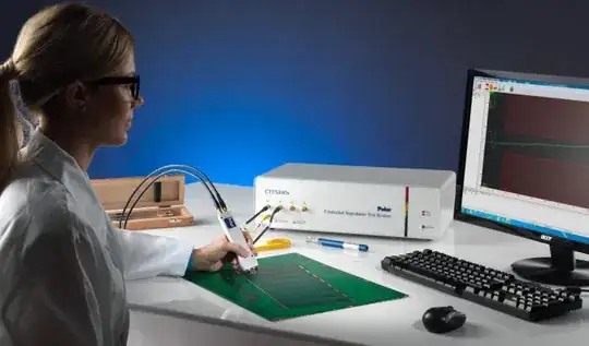
I prefer the TDR approach, I think you'll find your pcb house is likely using tools and software from polar instruments. These seem to be fairly popular in the fab shops, and they may only be testing the impedance at say 1MHz unless you specify something different.

enter image description here

Their goals are a bit different from an engineer who might want to understand the impedance over frequency, extract S-param models, or really understand or debug a specific trace. I'm not a fan of the VNA, it's a great tool, but can be complex for beginners to setup and calibrate. For PCB impedance work and model extraction I prefer the Lecroy Sparq. Under the hood it's a TDR but with a bunch of software to give you a more VNA like performance. Pretty easy to use.

enter image description here

You could try to make your own TDR if you have a good scope and a fast enough pulse generator. Not too long ago I had a good scope and no TDR, but I got a $100 high speed opamp from Analog devices with ps rise times. I was able to use that as the pulse generator and the scope as the receiver. It performed admirably for $100 :)

Some Hardware Guy
  • 15,815
  • 1
  • 31
  • 44