Summary
(1) Advice on running supplied circuit on lower voltage.
Reduce R2x slightly more than ratio of reduction in supply voltages for same LED current.
Max supportable LED current set by transistor beta (current gain) and R2x.
Increase C1x as R2x reduced to keep time constant constant.
- (2) Low voltage & component count any-LED flasher with other uses.
........ Details below
(1) Advice on running supplied circuit on lower voltage.
Your circuit can be made to run from lower voltage. Play with components and see what happens. See notes below for guidance.
With care you should be able to get it down to under 1 Volt without the LED loads. With red LEDs more like 3 Volts would be the lower limit.
This is your circuit. I've added component labels to the original.
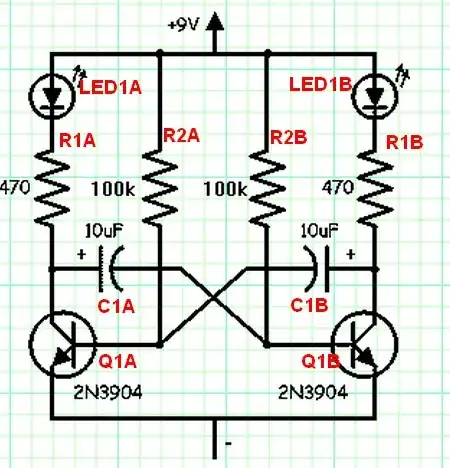
The circuit is symetrical with two identical halves - so I've named components with a and b suffixes. eg R1A and R1B serve the same function in the two halves, as do R2A/R2B, C1A/C1B, Q1a/Q1b. The *values of eg R1A and R1b may be different (see text) so the circuit may oscillate with different on times per half etc.
This is an astable oscillator. The oscillation periods are set by setting the OFF times of each half, rather than the on times. When eg Q1a is off Q1b is on so it may seem like you are setting on times but it is useful to know that in fact off times are being set.
LED current is set by ~ (Vsupply - VLED - Vsat_ Qx)/ R1x
Supply voltage needs to be the higher of about 1 Volt or Vf_LED + 0.5 to 1 V. eg with a RED LED with Vf of 1.8V then Vsupply >= ~ 1.8 + 0.5 = 2.3V. So, operation from 3V is practical.
Use term "Beta" = transistor_current_gain ((=hfE))
Ic_max = I_Base x Beta.
As shown base current Ib ~~= (Vsupply-Vbe)/R2x = (9-0.6)/100k = 84 uA.
For Beta = 100 then Icmax = 84 uA x 100 = 8.4 mA.
ie for transistors with Beta of 100 (= realistic value for many but not all "jellybean" transistors) max LED current =~ 8 mA.
If running at 3V and if LED current target was say 10 mA and Beta = 100 then
or R2x = (Vsupply-Vbe)/Ib x Beta = (3 - 0.6)/0.010A x 100 = 24 kohm.
R2A of 22K is closest value and perhaps 15k or even 10k would be wise.
Flash rate may now be set by calculating required time constant.
Say R2A = 15k. Say half flash time = 0.5 seconds.
RC = t or C = t/r = 0.5/15k = 33 uF.
This is only a starting point for reasons which can be explained if people are interested but gives some idea of what values to use. Note that at lower voltages R2x will get smaller to supply enough base drives so C1x will increase in size for the same time constant.
(2) Low voltage low component count LED flasher with other uses.
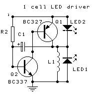
'Russell's' one-cell "any or many LED" flasher circuit.
- This can be not only a LED flasher or LED driver but a -ve or +ve low power voltage generator.
So also potentially a programmer supply, LCD bias supply, -ve opamp supply etc.
This circuit will flash an LED of any colour and forward voltage (or potentially even several LEDs in series) or will pulse a load using one cell - probably about 1 volt will be enough to operate it. I "designed" this circuit but it is based on a design that has not only long been used in transistor form but existed in pre-transistor thermionic valve days and, while I have never seen it used elsewhere, I would be surprised if it has not been independently "developed" by many other people.
As shown Q1 collector is driven negative below ground when Q1 turns off until energy in L1 is dissipated. Swap ground and supply and transistor types for +ve supply. Add diode from output to use as a DC supply.
L1 - small potted "resistor like" inductor or many others - experiment.
Q1 Q2 - almost any "jellybean" small pnp & npn transistors.
C1 polarised only to get high capacitance per size.
Can be eg ceramic if capacitance high enough for needs. Use only LED2 (best) or LED1 at one time.
- ...... Use either LED2 (most efficient) or LED1
Time constant ~= R2 x C1.
Long time constant leads to discrete flashes. Short time constant produce apparently permanently on LED.
Use resistor between Q1b-Q2c for higher supply voltages.
Resistor in series with C1 will extend pulse length.
This circuit is usually presented with a load of some sort in place of L1 - it may be an LED (depending on voltage or a transistor base (part of a following stage) or a light bulb etc. My 'innovation' was the very obvious one of using an inductor (L1) as the load. This provides a pulse of current into L1 when Q1 is on and when Q1 turns off L1 "flys back" and delivers whatever voltage is required to dump the energy from L1 into the load - here the load is one or other of the two LEDs shown. LED2 is the most efficient as it is powered by Vupply + V_L1 so part of the energy is stored in L1 and then released and part provided . LED1 if equipped is driven solely by V_L1.
(3) Other options
An LM393 dual comparator or its quad version can run on as little a 2 Volt and also do what you want. There will be flasher circuits using it on the internet.
LM339 quad version
prices
Once you "allow" the use of an inductor you can operate any LED from down to under 1 volt. Here's one way. I'll post more later.
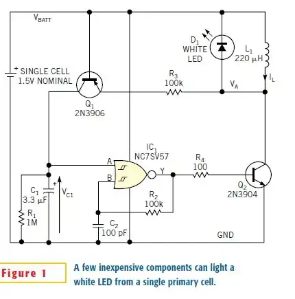
EDN White LED flasher operating from 1 cell
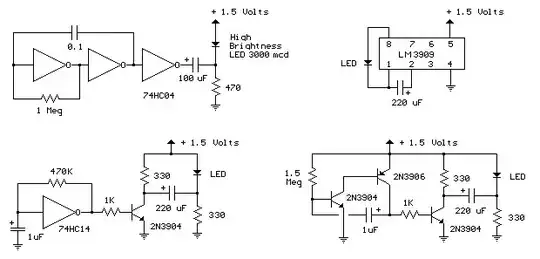
Here are 4 flashers stated to run on 1.5V.
The LM3909 IC is designed to flash an LED from a single cell. May be hard to find.
The 74HC04 and 74HC14 are probably at the bottom of their spec sheet power supply range at 1.5V so a single cell falls below that voltage rapidly. Quite likely to work at lower voltage but out of spec.
Circuit at bottom right will work at 1.5V and below.
Note that it is a variant of "my" 2 transistor + inductor flasher but they have added a transistor output buffer and do not have an inductor. Replacing the 330 ohm resistor with an inductor and removing the right hand 220 uF cap and 330 ohm resistor would produce a pulse at the right hand transistor's collector that would drive any colour LED.