 I am working on a project which requires me to amplify a dc supply volatge of 2v to 20v. I used the opa552 op amp with an input resistance of 100 ohms and a feedback resistance of 1k ohm (i.e., Rf/Rin = 10 is the gain). However I wasn't successful in getting the output of 20v with a single supply Vcc of 25v. The opa552 is designed to take supply voltages up to -30v to +30v. Basically am looking to amplify a dc supply voltage range of 0-5v to 0-30v. Please help
Asked
Active
Viewed 588 times
0
Sowmya Vidiyala
- 3
- 2
-
Can you show the schematic? This look like a simple non-inverter amp op config..... – MathieuL Jul 10 '15 at 14:57
-
The negative rail (V-) pin is connected to ground? If so then it sounds like you are violating the common mode input spec. For this op amp [the inputs must be 2.5V above V-](http://www.ti.com/general/docs/lit/getliterature.tsp?literatureNumber=sbos100a). – Null Jul 10 '15 at 14:58
-
Just to clarify - do you actually mean that you want to amplify a DC *signal* voltage? I only ask because we often see questions here where someone thinks that an opamp can produce an output greater than its own supply. – brhans Jul 10 '15 at 15:03
-
1feedback resistors are wayvtoo small. opamp has to source about 30 V/ 1.1 k = too much current. – User323693 Jul 10 '15 at 15:13
-
@Umar The op amp can output 200mA, so it can work with those resistors, depending on the load. They are wasting a lot of current and should be larger, though. – Null Jul 10 '15 at 15:19
-
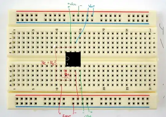
@MathieuL I have added the circuit diagram. – Sowmya Vidiyala Jul 10 '15 at 16:53
-
@Null Hey! I decided to supply it with a dual voltage supply of +20V and -20V, instead of a single supply. However I am finding it difficult to measure the output at pin 6. I do not know with respect to what I should measure the output ( which point should be my ground). My input is 4v and the output should be 12 V ( as Rf/Rin = 3k/1k = 3) – Sowmya Vidiyala Jul 10 '15 at 16:57
-
@brhans It is not a signal, it is the power coming directly from a DC source. We are using a DC power supply of 4v to directly feed as the input ( pin 2) of the opamp. Our +Vcc and -Vcc is set to +20V and -20V respectively. We want the output at pin 6 to be at 12v DC. – Sowmya Vidiyala Jul 10 '15 at 17:01
-
The - terminals of your supplies should be connected together and connected to the - terminal of the input. That is your ground; measure Vout with respect to it. It looks like that's what you're doing based on your drawing of the blue Vout lines. – Null Jul 10 '15 at 17:20
-
However your input + may not be right. You're showing it connected to Rin, but it should be connected to the non-inverting input of the op amp (pin 3). There's a red line connected to that pin but it isn't labeled. – Null Jul 10 '15 at 17:22
-
@Null, Hey thank you so much.I will try what you said. I have put the input to the non-inverting terminal initially as I just wanted to see if it actually amplifies the DC voltage. – Sowmya Vidiyala Jul 10 '15 at 18:11
1 Answers
0
Taking your picture as the actual version of what you're doing, rather than the obviously incorrect OP description, the following changes need to be made:
1) The + terminal of -Vcc and the - terminal of +Vcc must be tied together to form your ground point.
2) You must provide decoupling for your power supplies. At the least, a 0.1 uF ceramic must connect pin 7 to ground, and another must connect pin 4 to ground.
3) Since you now show your input voltage connected to one end of your resistor chain, you are creating an inverting amplifier, and your nominal output will be -12 volts.
4) Pin 3 (noninverting input) must be connected to ground, not left floating as you show.
5) You must keep your ground and power supply leads as short as you can, since this op amp is perfectly willing to operate at high frequencies. If your output seem to wander a bit, touch the op amp. If it is hot, you know that it is oscillating like crazy, and you need to consider getting a better class of breadboard.
6) I recommend using row 16 as a ground line, using a 1/2 inch long jumper to connect between the left and right sides of the breadboard. Make all of your ground connections to this new ground line, especially your decoupling capacitors and your noninverting input, and keep them as short as possible.
WhatRoughBeast
- 59,978
- 2
- 37
- 97
-
Hello WhatRoughBeast. Thank you so much for your suggestions. We implemented all of the above and did a non inverting amplifier with a gain of 5. The circuit worked!. We connected a 0.1uF to pins 7 and 4 along with a load resistor of 10kohm at pin 6. Thank you so much again – Sowmya Vidiyala Jul 13 '15 at 14:49