7

I am trying to measure average current draw of low-duty cycle, low current devices.

For example, a Bluetooth Low-Energy device might draw 16 mA during the radio transmissions (for a millisecond or so), and background / idle current at other times, say 3 uA.

These transmissions happen infrequently. So taking a current reading with a DMM that updates once per second gives wrong readings, because the DMM does not have a proper anti-alias filter, so the reading depends on whether one or two radio transmissions happened during the DMM's sampling period.

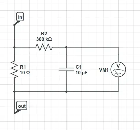
To measure this current I have been using a custom-designed circuit, an external shunt with an RC across it, where the RC is set to several seconds. Then I measure across the "C" on a low-voltage range of a voltmeter.

enter image description here

Are there any ammeters with proper anti-alias filtering? I have tried Keithley sourcemeters and HP34401 meters, and neither will do it. (The Keithley has a triggered current measurement mode, which at least gives a stable reading, but this won't give an accurate average reading.)

markrages
  • 19,905
  • 7
  • 59
  • 96
  • What kind of accuracy/resolution are you looking for? You might be able to use something like a 16-bit DAQ with a few ksps, or even build an analog integrator circuit. – helloworld922 Jul 08 '15 at 21:12
  • 1
    Not a recommendation necessarily but my 34410A has anti-alias filtering in true RMS mode. Maybe it's time to upgrade, that 34401 is pretty long in the tooth. – Spehro Pefhany Jul 08 '15 at 21:24
  • @SpehroPefhany does the 34410 have the schematic in the manual? That's my first requirement for DMMs. – markrages Jul 09 '15 at 02:15
  • 1
    I don't think it's in the manual (probably only PDF manuals). The 34401 came with beautiful hard copy manuals including full schematics. The 34410 schematic did show up in the Keysight forums [here](http://www.keysight.com/owc_discussions/servlet/JiveServlet/download/123-36971-112352-6830/schematic.pdf) – Spehro Pefhany Jul 09 '15 at 03:04

3 Answers3

2

This is a difficult problem. What I have done in the past is measure the current during the brief high current event using a current probe on an oscilloscope. In my case, the current profile was the same every pulse. So then I integrated to figure out how many coulombs each pulse is. Then I could just count the pulses. In my case, the current consumption in between pulses did not make much difference to battery life (which is what I was trying to figure out), so I could just ignore it. But you should calculate it to be sure. An ammeter should be fine for measuring current between pulses.

If your current pulses are variable in length or amplitude, this approach may not work very well.

Another idea is to use a rechargeable battery of known capacity and measure time until the battery reaches the termination threshold (you can log VBAT with a logging voltmeter). This is probably what you are trying to figure out anyway, right, battery life? In any event, if you use a small battery, that could allow you to get a reasonably good answer in a reasonable time frame, as long as the battery can supply the pulse current without excessive drop.

Things to consider are the variation of current with voltage (in my case it was constant current, but if you have DC-DC converters it may be more like constant power).

Good luck.

user57037
  • 28,915
  • 1
  • 28
  • 81
1

I do something similar, but using a filter on the power supply itself.

Connect a large capacitor to supply the device, and a significant resistor between the external power supply and the capacitor. Now measure the current through the resistor, I used a regular multimeter on the 2 mA scale.

Select R to get a 0.25 volt drop at your expected average current, and then C for a time constant of perhaps 10 times the length of your micro's sleep/wake cycle. I think I used 10,000 uF and a few kOhm.

For booting up and flashing if the microcontroller, you'll need to bypass the resistor or connect a much lower value in parallel, otherwise the supply voltage will drop too much. The nice thing is that you can do this without disrupting the supply. Then when it is safely asleep, remove the crocodile clips across the series resistor.

tomnexus
  • 7,617
  • 3
  • 19
  • 35
  • Check the leakage current of the 10mF cap, since you are measuring its leakage added to the load current. – markrages Jul 09 '15 at 03:35
0

If you know that the only two situations are TX -> 16mA and NOTX -> 3uA and you can perform an accurate measurement in those two cases, then you could rig up a system that simply measure the duty cycle of the process.

In particular, if you accumulate the total TX time \$T_{TX}\$ over a much longer time \$T\$ in which \$N\$ transmission events are triggered you could compute the average current as:

$$ I_{avg} = \dfrac{I_{TX} \cdot T_{TX} + I_{NOTX} \cdot {T_{NOTX}}} T = \dfrac{ I_{TX} \cdot T_{TX} + I_{NOTX} \cdot (T - {T_{TX}} ) } T $$

Note that \$N\$ should be large if the single transmission event has not fixed duration. The more \$N\$ is large the more accurate \$I_{avg}\$ will be. This shouldn't be too difficult: even an Arduino board can be programmed to measure long times, just connect a buffer circuit between your current sense resistor and the MCU ADC, then poll continuously until you detect a surge in current (TX is on). If the ADC conversion time is too slow, you could connect an analog comparator to your sense resistor, and use its output as a digital input on the MCU, then poll it continuously. The only problem is to make enough polls per seconds to have an accurate time reading, but if your transmission events are relatively long compared to the polling period, then you should be OK.