12

I know that a transistor amplifies a signal, but I've never used one. I have this design here and I want to add 15 LEDs connected to each pin, instead of 1.

How I could incorporate a transistor to help me achieve a strong enough current to power the LEDs ?

James C
  • 652
  • 2
  • 9
  • 19
Mike
  • 583
  • 1
  • 7
  • 17
  • This question is kind of a duplicate of this one: http://electronics.stackexchange.com/q/6093/3803 – Tall Jeff Aug 08 '11 at 00:36
  • This question adds the unique constraint of the vu-meter ic's active-low open collector outputs, vs. the PIC's output and active hi/low flexibility. That means *directly* driving NPN transistors is out. – Chris Stratton Aug 08 '11 at 00:45
  • Would a PNP transistor work instead of a NPN? – jsolarski Aug 08 '11 at 01:09
  • ...PNP: Yes. The original LEDs are Vdd (V+ , Vhigh, Vsupply ...) referenced. If you don't mind them being ground referenced instead then a single PNP per channel would work.LM3915 drive PNP base via a resistor. Each PNP emitter to Vdd. Each PNP collector via a resistor to LEDs. LED cathodes to ground. Resistor per LED is required as, while LM3915 current limits the LED current, the transistors do not. While it is notionally possible to common transistor emitters and use a single resistor for 2 or more transistors, this is a bad idea for several reasons. – Russell McMahon Aug 08 '11 at 05:30
  • Don't think of a transistor as "amplifying a signal". Think of it as a valve that can be opened or closed. It's used as *a component of* amplifiers, but it can be used in switches or other things, too. – endolith Sep 07 '11 at 21:22

1 Answers1

11

The simplest solution would be to place the 15 LEDs in series and use a high enough power supply. The "high enough" is the problem here. You would need at least 30V and that's too much for the LM3915. Placing the LEDs in 3 parallel strings of 5 LEDs each isn't a solution either; the LM3915 can't sink enough current to drive the 3 strings.
So we'll need external transistors. The driver's outputs are most likely open collector NPNs. Then this schematic should work:

enter image description here

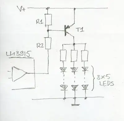
If the LM3915's output is low (LEDs must be on) T1 will be switched on via R2 and supply current to the LEDs. Those could have been placed in a single string, but then you would need a too high voltage for V+. Now 12V will be sufficient for common red LEDs.
If the LM3915's output is switched off R1 will pull the base of T1 to V+, and T1 will be switched off.
The components' values will depend on V+ and the current required for the LEDs. For V+ = 12V you could make R1 = 1k\$\Omega\$ and R2 = 4.7k\$\Omega\$. This will give a base current of 2mA, which is enough to saturate most transistors, so T1 can be a PNP type like a BC556.

stevenvh
  • 145,145
  • 21
  • 455
  • 667
  • and what if 20 LEDs are in parallel? – Mike Aug 08 '11 at 23:35
  • @Mike - same thing, just add another string of 5. You'll have to start thinking of the transistor's limits, though. The BC556 is limited to a collector current of 100mA, so for 20mA LEDs that's still OK, for more I'd split the circuit over two transistors, each driving 10 LEDs. Just double everything, including R1 and R2. A more sturdy transistor is also possible, but this will be cheaper. – stevenvh Aug 09 '11 at 05:45
  • @stevenvh what happens if I try to replace the led series with a relay? Can you please confirm if a relay can be controlled by LM3915 using this additional circuitry on the output terminals? All I am trying to achieve is driving AC loads with LM3915. – sribasu Sep 25 '22 at 06:04