3

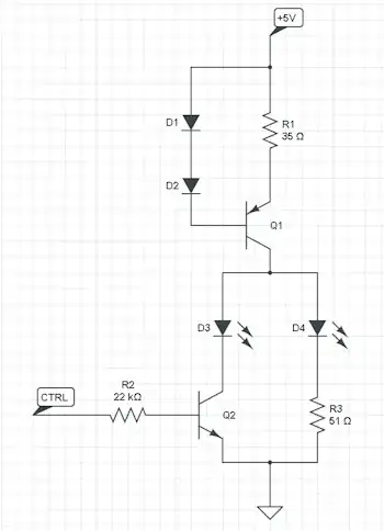
I have a simple preamp circuit coupled with a class AB power amp. The design is quite simple and I am pretty sure I already made it work a couple of years ago.

schematic

simulate this circuit – Schematic created using CircuitLab

The power transistors are the TIP31C and TIP32C.

While the preamp works correctly, when I power the class B amp, some components burn:

  • TIP31 (always);
  • C3 (often);
  • C2 (always);
  • D1 (always);
  • C4 (some times);

The load is an electromagnet; the 50/-50 V supply is required for the electromagnet to work. It should consume no more than 1.5A at full duty.

I think that there is no wiring error in the circuit since a friend and I triple checked it.

Finally, the DC supplies are both independent lab supplies, floating and not connected to earth.

So, something wrong with this circuit? (obviously... ;) )

EDIT:

Here is the result of a 3s frequency analysis. I reversed the polarity of C2 and C3 and I removed L1 since Circuit Lab could not simulate with it.

enter image description here

What puzzles me is that the output of the preamp (blue signal) doesn't have the same amplitude than what I measured with the oscilloscope. I measured a signal with a 26-27V DC bias and a 4V bottom and 49.8V top swing (sorry, I don't have a picture right now).

I will simulate with OrCAD Pspice and see if there is another result...

Doombot
  • 282
  • 1
  • 11
  • Couple things are wrong with the circuit as drawn: C2 and C3 are reverse polarized, C4 should not be required unless you made an error with the power supplies and ground. – jippie Jul 06 '15 at 17:42
  • Dan is right about the transistors. If you are able to actually drive the transistors near the rail, it is bad practice to use them so close to the maximum V(CE, max)specifications. – jippie Jul 06 '15 at 17:43
  • Top of mind, the top transistor Q2 cannot be driven higher than approximately +25V. Say h(FE)= 25, R6 = 37 ohm. Order magnitude at the base of Q2 is order magnitude of R2. – jippie Jul 06 '15 at 17:46
  • Q1 can easily be pushed beyond its limits. Say 25V is across the transistor, that leaves 25V across the resistors. Current will approximately be 25V / (510+51) = 45mA. 45mA × 25V = 1.1W. However, Q1 transistor will probably be saturated, because its base current is too low. – jippie Jul 06 '15 at 17:51
  • You have drawn the circuit in circuit lab. Try DC analysis and see what happens at the various nodes. It'll be a good exercise. There is only one way to learn electronics, and that is learning from your mistakes. You have couple pointers what to look for now, I'm sure people are willing to help with your findings and improve your circuit. – jippie Jul 06 '15 at 17:54
  • Thanks I'll try to change the caps polarity and to simulate it, and keep you posted! – Doombot Jul 06 '15 at 18:02
  • How can this be AB, with only one diode drop of bias across two BE junctions in the output stage? Looks like class B. Since you have no global feedback, this will have a lot of crossover distortion. – Kaz Jul 06 '15 at 21:21
  • Yes this was a poor AB design, I added a second diode... – Doombot Jul 06 '15 at 21:45
  • Do your DC analysis before your AC analysis. Check if all node voltages and the currents make sense. Calculate power dissipated in the components and check if those make sense too. Also it would be good to first try to estimate the various voltages and currents by yourself, then verify them against simulation results. – jippie Jul 07 '15 at 06:40

1 Answers1

3

I see a few problems.

  1. As Jippie says, C2 and C3 are reversed. The collector of Q1 will be biased somewhere between +50V and ground. The bases of your output transistors should be biased somewhere close to ground.

  2. Your preamp biasing looks a little suspect. With a minimum beta of ~75 (from the datasheet), Q1's collector would barely get down to 10V below the supply voltage. If you want a 10V output swing, that's not a lot of room. The transistor you have in the circuit right now might work, but it probably won't be reliable.

  3. You might need more than one diode between the output transistor bases. Your diode voltage is going to be ~1V, but your Vbe drops will probably add up to ~1.5V.

Finally, make sure you stay within the safe operating area of the TIP31s (from this datasheet):

TIP31C Safe Operating Area

Adam Haun
  • 21,331
  • 4
  • 50
  • 91
  • 1. Right now, experimentally, at the output of the preamp, the bias is around 26-27V and the amplitude varies from 4V to 49.8V. It is possible the input sine signal is bigger than 1 Vpp, I am no longer at the lab so I'll check later – Doombot Jul 06 '15 at 18:25
  • 3. I'll try that, you're right! – Doombot Jul 06 '15 at 18:28
  • 1
    Your current bias is consistent with a beta of ~200, which is reasonable for that transistor. It's usually better to bias with a voltage divider instead of a base resistor. C1 might be too small -- at 5 Hz it's equivalent to about 3000 ohms. Instead of AC-coupling everything, have you considered using a different transistor and biasing the collector halfway between the two supplies (i.e. at 0V)? – Adam Haun Jul 06 '15 at 19:40