You would need a max of 4x5 = 20 inputs not 25 as the common pin is not sampled, but less is certainly possible (nine in the answer above).
You could connect 4 different value resistors to each pin and use them to generate a variable potential divider and read each switch with a single analogue input. You would need at least 6 bits of resolution to get unambiguous results, 8 bits would be easier as the resistor selection would not be as restrictive because your input would be maximised at half of the supply (though you could tune it to close to a lower vRef if available when at the max decimal value).
If you have the analogue inputs you could get away with 5 inputs, less if you add a multiplexor. You could use a 8 input MUX and a single count pin to drive a 3 bit counter to select the input. Connect up to 6 inputs to the mux and have the first input set to 0V and the last to Vcc and then the other 6 inputs would be at values between these (you could add one more resistor to bias the switch inputs above zero so your start and end channels are unique. This lets you get away with one output (shared with a status LED or something possibly) and one analogue input (the mux could input one other slowly varying signal on the spare pin like a current limit pot value or something) and some software.
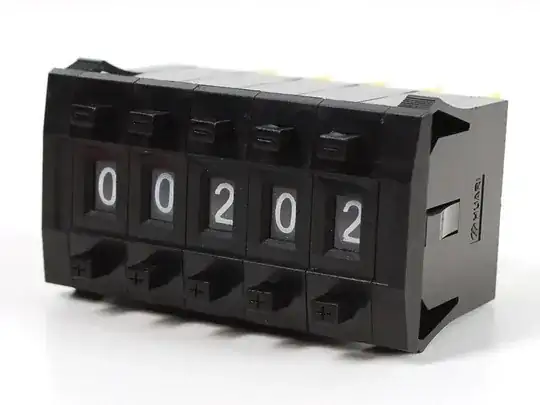
As these are probably decade input switches you could use just one input to the mux as a framing voltage that you equate to the HEX 'F' value that cannot be generated by the switches. This will allow you to read 7 decade switches (instead of 6 HEX switches) with an 8 input mux. If you read all the switches twice and resolve the same setting you can be fairly secure in knowing that they have not been in the process of changing. The R2R or the 1R, 2R, 4R, 8R methods will both work, one has more components but can be just one or two resistor values, the other has fewer but possibly odd values.
If you have a 10 bit resolution analogue input you could possibly resolve 8 bits of resolution and do 2 switches with each signal or a total of 14 decade switches with 2 pins, perhaps not as reliable though.
Links to two answers here that will explain how to do it and the last link will show you lots of possible implementations if the above is not suitable or clear enough.
BCD Switch Resistor Network for Proportional Voltage Output
How should I use rotary switches and resistor networks to uniquely relate each possible combination of switch settings to an analog voltage?
https://www.google.com/search?q=bcd+to+analogue+resistors&tbm=isch&tbo=u&source=univ&sa=X&ei=kseWVYCvGMi1sQHzj4PwCQ&ved=0CCwQsAQ&biw=1400&bih=778#imgrc=JjeuJK-k9gTQsM%3A