6

I want to measure absortion/resorbtion currents of dielectric when applying 1000V, 1500V, 2000V.

I have made a small currents measuring device using a LOG114:

enter image description here

enter image description here

enter image description here

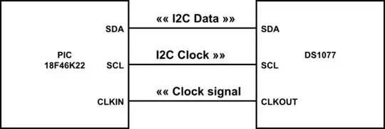
I use : LOG114 with 1uA reference current on input I1. The power supply for the LOG114 is made using an 78L05SMD (12V -> 5V) and after, the ICL7660 to get the -5V. The logarithmic output of the LOG114 is scaled to 0V..2.5V and feeded to the 24bit ADC LTC2400. I use an microcontroller to get the readings and send to computer for further processing.

The problem is how do I connect this device to measure capacitor charging/discharging?

If I use for example a simple current source made of a 1.5V battery and a 91Mohm 5% resistor, I get correct readings of current 16nA.

I need help me adapt this to measure charging and discharging of a capacitor.

I have found this board used by someone to measure this currents but no explanations, it is using the LOG104 :

enter image description here

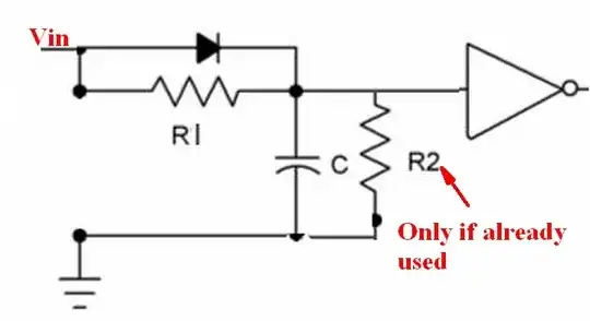
I made the schematics:

enter image description here

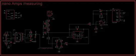
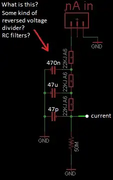
The connection of current input is like this on the board that person uses:

enter image description here

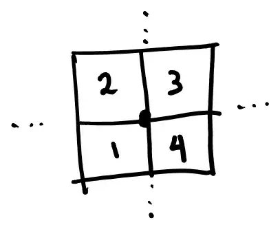
The question is what is this:

enter image description here

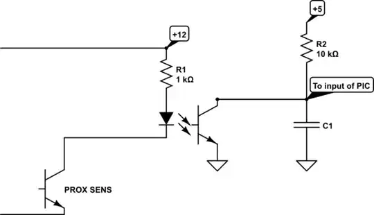
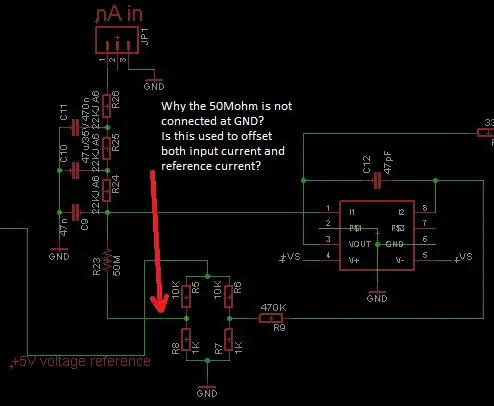
Why the 50Mohm resistor is not connected to ground, are those voltage dividers of 10K/1K from the 5V reference used to offset both input current and reference current that goes to LOG104?

enter image description here

1 Answers1

2

First, the direct answer. You need to connect your circuit between the lower end of the lower 1M resistor and ground. Any charge or discharge current in the cap also flows through both 1M resistors.

Now, about your other circuit.

R6/R7/R9 sets the reference current at about 1 uA.

R23 provides a 10 nA offset. Apparently the input current is expected to occasionally go negative. Alternatively, the designer wanted to guarantee that if the current goes to zero, the resulting output could be identified as that condition.

The R24/R25/R26/C9/C10/C11 provides a comprehensive low-pass filter for the input current. The varying capacitor values avoid problems with self-resonance at any particular frequency.

EDIT -

My direct answer referenced your resistor/capacitor diagram, and the result should look like

schematic

simulate this circuit – Schematic created using CircuitLab

You will note that the LOG114 should not be connected where you think it should. It is connected at "the lower end of the lower 1M resistor", just as I stated.

And I agree that if you try to apply the low-pass filter to the top of the lower 1M resistor, and add a 50M resistor after that, you will get a lower current. But that is irrelevant, since you don't want to do it in the first place. Attempting to infer current by measuring the voltage across the lower 1M resistor is a supremely bad idea - at the very least, a 100 uA current will produce 100 volts, and I can't think of a good way to attempt to measure that.

You are attempting to adapt a circuit approach which is inappropriate to your problem.

WhatRoughBeast
  • 59,978
  • 2
  • 37
  • 97
  • could you please be more specific about connecting the LOG circuit to the end of bottom 1Mohm resistor. Also If I simulate the circuit using 2KV supply,the two 1Mohm resistor,the capacitor under test and connecting the low-pass filter made of R24/R25/R26/C9/C10/C11 and 50Mohm resistor, the current after the low-pass filter it is not the same as the one that goes in the low-pass filter. It is smaller. – Nedelcu Bogdan Jul 05 '15 at 18:51
  • @NedelcuBogdan - Please see edit. – WhatRoughBeast Jul 06 '15 at 04:55