1

I'm working on a circuit design with a microcontroller that runs on 3.3V. I'd like to be able to power it either through a 3.3v supply or a USB port. I'm using an spx3819 regulator.

What would be the best way to achieve this? What I have in mind so far is something like this:

schematic

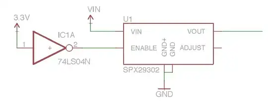
Basically, the 3.3V signal is fed into an inverter, which disables the regulator. This 3.3v signal is also directly fed into the microcontroller (not shown in the schematic).

Is there any better way?

EDIT: The Vout is directly fed into the microcontroller. Vout is 3.3v. When high, the 3.3v source will disable the chip, regardless of the voltage at Vin (the enable pin disables the chip at < 0.4v).

Malfunction
  • 145
  • 2
  • 8
  • 3
    Where does Vout go? If it's supplying the 3v3 net, you just created an oscillator with an inverter and an LDO. – Nick Johnson Jul 02 '15 at 10:36
  • @NickJohnson Alternative part use. It is not to be snubbed at. ^.^ – Asmyldof Jul 02 '15 at 10:49
  • When supplied by 3.3 V, how does the 3.3 V get to the microcontroller ? You could use 2 diodes to solve this by combining the vout of the regulator with the external 3.3 V but you will get a small voltage drop (0.2 V when using shottky diodes) so the microC. would then be running at 3.1 V. – Bimpelrekkie Jul 02 '15 at 10:51
  • You haven't specified which you want to have priority, either: the 5V USB supply, or the 3v3? – Nick Johnson Jul 02 '15 at 10:53
  • What is VOUT value? – User323693 Jul 02 '15 at 12:03
  • Why you don't just use a switch? – MathieuL Jul 02 '15 at 12:12
  • "the 3.3V signal is fed into an inverter ... This 3.3v signal is also directly fed into the µC" - You'll need a diode or two anyway in this case, or the regulator will oscillate rapidly turning itself on and off when USB-powered. – JimmyB Jul 02 '15 at 13:28
  • Also, I can't seem to find info in the datasheet about how the LDO handles Vout > Vin, or Vout > GND when disabled. Needs to be checked. – JimmyB Jul 02 '15 at 13:31
  • I've updated the question with some clarification. – Malfunction Jul 03 '15 at 10:37
  • @IC_designer_Rimpelbekkie Why would I need any diodes? When the external 3.3v is active, the regulator is disabled, and there's no output on Vout. – Malfunction Jul 03 '15 at 10:39
  • no output on Vout, with that I agree. Now how does the 3.3 V get to the microprocessor ?? Vout (which is the 3.3 V for the miscroprocessor, right ?) is now off. Using diodes you can feed whichever voltage is higher (external or internal 3v3 ) to the micro. – Bimpelrekkie Jul 03 '15 at 12:38
  • @IC_designer_Rimpelbekkie Oh, so you mean diodes on both the 3.3v source and Vout? – Malfunction Jul 03 '15 at 15:13
  • Yes, something like the 2nd picture here: http://electronics.stackexchange.com/questions/130986/automatically-switching-from-9v-battery-to-dc-wall-adapter-on-insertion That uses 9V and 12V but it should also work here. – Bimpelrekkie Jul 04 '15 at 11:58

2 Answers2

1

I know the answer is subjective.
I use this whenever there is a need to switch between two supplies with at least 1 V difference automatically. Here, assuming VIN_EXT is less than 5 V, the circuit will draw power from PC whenever USB power is available, else from VIN_EXT automatically.

schematic

simulate this circuit – Schematic created using CircuitLab

Major advantage here is that, drop across the FET will be just a few 10s of mV at max compared to diode drop of about 300 or 400 mV

User323693
  • 9,151
  • 4
  • 21
  • 50
  • This doesn't seem to be working when I try to simulate it and I don't see a way how it could. Can you elaborate on the design? – ja2142 Jul 01 '19 at 19:20
  • @ja2142 the P Mosfets are basically just acting like diodes. Assume there is no USB power. – User323693 Jul 23 '19 at 18:12
  • @ja2142 the P Mosfets are basically just acting like diodes. Assume there is no USB power. M1 body diode will conduct and soon after M1 turns on as VGS will b positive... when SUN power is introduced, M2 will power on as it is strongly biased than M1 thereby blocking M1... May I see your simulation once? – User323693 Jul 23 '19 at 18:19
  • When I connect voltages to both VIN_EXT and usb 5v intput (eg 3V and 5V respectively) there is large current from USB to VIN_EXT. – ja2142 Jul 24 '19 at 19:47
  • Please check the PMoS connection. The Source and drain pins might be swapped in your circuit – User323693 Jul 26 '19 at 03:25
  • https://ibb.co/JKt5ybM – ja2142 Jul 28 '19 at 13:13
  • i could only find a savage solution for now. Connecting two MOSFET in parallel was a mistake from my side. Thanks for pointing out and for your time – User323693 Jul 29 '19 at 21:34
-1

A simple solution is just to use a switch, if you don't mind to flip the button. This image is taken from the Tiva C LaunchPad, a simple switch between the USB_VBus and the In Circuit Debug Interface.

enter image description here

MathieuL
  • 1,126
  • 1
  • 9
  • 22
  • 1
    Using a switch is not an option, as it would complicate the design. – Malfunction Jul 03 '15 at 10:40
  • Then use a relay, power the relay from Vin, if the Vin is off, let the relay connect the supply of the micro to the external 3.3 V supply. – Bimpelrekkie Jul 03 '15 at 12:40
  • Vbus = Vin which connecte to both Vin & enable of your LDO, I don t see how it would complicate the design. – MathieuL Jul 03 '15 at 14:51
  • 1
    I honestly don't want to bother the user with any more switches, and since the final circuit will be used in a restricted, portable environment, relays are off the table. – Malfunction Jul 03 '15 at 15:15