I was reading the question here with some interest, because I am in the end stages of construction on a project that involves 16 solid-state relays. I'm using non-zero crossing type, because that's what I happened to find on a schematic by someone who completed a very similar project to mine.
The datasheet for my SSRs mentions that a snubber circuit is recommended, especially when driving inductive loads (which I am, since my loads are AC solenoids). I thought I understood that this is to give somewhere for the energy stored in the inductor somewhere to go if the SSR switches off right as the voltage peaks. When I read about ZC-type SSRs, I thought to myself, "self, that would eliminate the need for a snubber circuit, right?"
I then dug up a datasheet for the ZC version of the SSR I'm using, and I found this:
Particular attention needs to be paid when utilizing SSRs that incorporate zero crossing circuitry. If the phase difference between the voltage and the current at the output pins is large enough, zero crossing type SSRs cannot be used.
As well, the snubber circuit continues to be recommended for the ZC-type SSR.
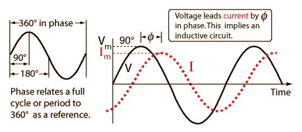
The phrase "phase difference between the voltage and the current" doesn't make sense to me. What does that mean?