2

In a nutshell :

  1. My circuit behaves erratically
  2. I connect the 'scope to find out why
  3. The problem disappears

In particular, this concerns the circuit in my last question although this is not the first time it's happened to me and I'd like to know what's the correct way of finding the source of this general problem. In software, we'd call these Heisenbugs but I don't know if the same pun is used for EE problems.

In this particular instance, I have a test program running on the PIC that goes from 0% to 100% duty cycle on the PWM output in 8 steps, pausing for 10 seconds at each step. Then it goes back down again from 100% to 0%. The problem is that it goes up ok, but gets stuck coming down - i.e. the fan doesn't fall in speed as it should.

Just connecting the ground of the probe to my circuit ground fixes the problem, even without the scope switched on. When the scope is connected and running, all probed signals look clean and tidy and everything works perfectly.

I'm guessing that I'm picking up some interference from mains hum or from the power supply, but without being able to observe it when it's misbehaving, I don't know what it is I should be fixing.

What do I do next?

Schematic:

schematic

Board:

board

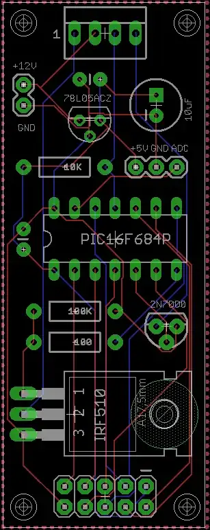
The 2x5 header at the bottom is there just to expose all of my unused PIC pins in case I want to extend this in future (it's a hobby project). Fan connector is at the top.

Roger Rowland
  • 2,002
  • 4
  • 18
  • 36
  • Seems like tying GND to mains earth will fix the problem. If you just want to solve it and thats an option, just do it. If you want to know the reasons, we need to know far more about your setup, depending on what the problem is the schematics are sufficient or more like the actual pcb layout is needed. Also dont forget to specify exactly what is connected where and how to your pcb. – PlasmaHH Jul 01 '15 at 09:24
  • The ground of your oscilloscope is connected to mains earth. On most lab supplies the supplies are floating with respect to mains earth but most do have a ground connection on the front. Could you try what happens when you connect this ground to your supply (minus side usually) ? – Bimpelrekkie Jul 01 '15 at 09:25
  • @PlasmaHH Thanks, I'd really like to know how to find the problem i.e. what are the next debugging steps. The schematic is in my linked post but I've included here to save clicks and also the board layout (auto-routed, so expecting some comments!). See edits. – Roger Rowland Jul 01 '15 at 09:43
  • @RogerRowland: What can be done independently from analyzing the circuit is trying other means of powering it, like a different power supply, or a battery. Or put things into a metal can if you suspect it to pickup something. If you want to debug it without grounding it, this might be one of the cases where you could run your scope with an isolation transformer if you know what you do. – PlasmaHH Jul 01 '15 at 09:52
  • @IC_designer_Rimpelbekkie Yes, my PSU has a separate green Earth terminal, and if I tie that to the negative output, it also cures the problem. What does that imply? – Roger Rowland Jul 01 '15 at 09:58
  • Are any of your external signals connected to GND (or not fully isolated from them?) I'm looking at FANGND on the sch... –  Jul 01 '15 at 10:01
  • @BrianDrummond Nothing connected to FANGND, but as it happens, that *was* the point I attached my probe ground when it got things working. I should perhaps have chosen the other side of Q2? EDIT - just tried it, it still cures the problem. – Roger Rowland Jul 01 '15 at 10:04
  • Given the comment thread, I've edited my answer. I think your power connections may well be wrong. – Scott Seidman Jul 01 '15 at 12:56

3 Answers3

2

There are three main possibilities --

  1. there is some external system you're connecting to, and you haven't passed a reference voltage between your circuit and this system. If the external system is connected to earth ground, when you attach the ground of your scope cable to your circuit, you are now passing a reference and fixing the problem. (my first bet if I were a betting man).
  2. Something wants a little more capacitance and the scope probe is providing it
  3. Some spurious currents are looking for a better path to ground, and the earth ground is providing it.

The first option is probably debuggable by extension, the second by adding caps as others have described. The third might be caused by currents associated with voltage spikes associated with PWM control of a motor, and missing the diode you need to deal with this. You might consider just replacing the fan with a few resistors (i.e., a non-inductive load) in parallel (sufficient number to deal with the power generated) and see if the problems go away.

One more issue-- You may just have your power wired up incorrectly. If GND in your circuit is chassis ground (i.e., the "Ground" jack on your power supply), and there is no internal connection between V- and ground on the supply, you need to make a connection between chassis ground and V- or there is no reference to V+, or, instead of hooking your circuit ground to chassis ground, you use V- for GND in your circuit.

Scott Seidman
  • 29,274
  • 4
  • 44
  • 109
  • Thanks Scott. I'll try to cover your points: 1) there's no external system, just this one; 2) the scope ground is enough to fix the problem, the probe can be unconnected; 3) sounds promising. Tying my PSU V- to its GND fixes the issue in the same way but I'll be running from a double insulated wall-wart, which doesn't have a "true" ground and also shows the same problem as the bench supply (when floating). I can't really replace the fan with resistors because a) that's the only way I see the problem and b) the fan's pull-up is required anyway. – Roger Rowland Jul 01 '15 at 14:52
  • You won't have this trouble with the wall wart. – Scott Seidman Jul 01 '15 at 16:00
  • I *do* have this problem with the wall wart. In fact that was my original configuration. – Roger Rowland Jul 01 '15 at 16:37
  • @RogerRowland Can you be real specific about your power connections?? – Scott Seidman Jul 01 '15 at 16:38
  • Sorry Scott, I thought I had been clear. My original problem occurred when powered from 12V switching wall wart. I then tried with a linear bench supply, same problem. Following Rimplelbekkie's suggestion, I tied the V- and Earth on the bench supply and that cures the problem. With either supply, attaching scope ground to circuit ground also cures the problem. Does that help? – Roger Rowland Jul 01 '15 at 16:41
  • *How* did you connect the bench supply before you connected V- and chassis Ground? What *exact* connections did you use? – Scott Seidman Jul 01 '15 at 16:43
  • I tried banana jump leads from linear supply terminals to jacks on breadboard, then DuPont jumpers from breadboard to 12V and GND at top left of board. Breadboard had nothing else on it. I also tried putting the duponts directly to the bench supply screw terminals, so only 4 inches. No change to the problem in either case. – Roger Rowland Jul 01 '15 at 16:50
  • @RogerRowland -- I have the connections on your board. What are the exact connections on the Power supply. What supply terminals? V+ and V-, or V+ and GND?? – Scott Seidman Jul 01 '15 at 16:54
  • V+ and V- on the power supply. However, if I *also* connect V- (on the power supply) to the power supply Earth terminal (a separate green terminal right beside the black and red), then it works ok. – Roger Rowland Jul 01 '15 at 17:17
1
  1. Unlikely, but easiest: Try a 10 µF capacitor acorss the input of you 78L05. Chances are that your supply (5 V) becomes unstable, causing the microcontroller to... um... go all Heisenberg?

  2. Very (!) likely: Also, a somewhat bigger capacitor acorss your 12 V supply in parallel with a low-impedance capacitor (e.g. 100 µF electrolytic, 100 nF ceramic) across your 12 V input is a really good idea. Your fan motor looks much like an inductance, and the spikes created when Q2 turns off might disturb your 5 V regulator and/or your microcontroller. Ideally, connect them such that the loop from the positive end of the cap to the output of the fan, and from Q2.source to the negative end of the cap becomes as small as possible.

  3. Very likely and really a thing you should try, too: Put a (fast!/Schottky!) diode from Q2.Drain to +12V, with the anode connected to the drain and the cathode to +12V, right where your capacitors are. This diode will catch the spikes and clamp them onto the capacitors you just added in (2). You can actually probe from Q2.drain to ground and check if the drain spikes go way above 12 V, or maybe even above Q2's max. allowed drain voltage.

zebonaut
  • 18,170
  • 4
  • 60
  • 104
  • That's useful, thanks - now I have somewhere to go and some things to try. As the problems go away with the grounding, do think it's more likely a noise problem than a problem with supply? – Roger Rowland Jul 01 '15 at 10:50
  • 1
    Hmmm... Likely a problem with noise *on* the supply, caused by the properties of your load (a switched iductance). What hints at this is that your circuit starts o.k. and goes berserk just after it has already run well. Let us know if 1, 2 and/or 3 did the trick ;-) – zebonaut Jul 01 '15 at 10:55
  • Ok, I'll get stuck in to this and will update later. Many thanks for the advice. – Roger Rowland Jul 01 '15 at 11:11
  • Note... My answer was written assuming Q2 is the output to the fan and Q1 unused (I'not sure what you actually do with the small FET)... – zebonaut Jul 01 '15 at 11:21
  • Ahhhh. Actually Q1 is the PWM and Q2 is used just to kill the power to the fan completely because it has a minimum speed below a certain duty cycle. In this 4-pin fan, there is a separate PWM control line, which is what I'm controlling via Q1. – Roger Rowland Jul 01 '15 at 11:24
  • ... sooooo: Q2 is basically always on when your fan runs? Your fan has an internal circuit that reads your pwm, filters/converts it to a voltage, and a motor driver that controls the speed proportional to the pwm? If Q1's output is just a control/logic input to the fan, my answer might still if you replace Q2.drain with X1.2 (except for "3", which would then hopefully already installed inside the fan's electronics), because any spikes created by the fan's internal power stage might still appear at X1.2 (which I then read as the 12 V supply to the fan). – zebonaut Jul 01 '15 at 11:35
  • Yes, Q2 is always on at duty cycles above ~15%. The fan has some unknown circuitry that - from testing - has a pull-up to 12V on its PWM line. So I use Q1 to pull it down according to my PIC's PWM output. I'll do some work around your suggestions and let you know .... – Roger Rowland Jul 01 '15 at 12:14
1

With due respect, regardless of what the scope ground does, your layout is abominable.

Particularly when PWMing, you MUST maintain better ground routing. As it stands, current from the sources of your FETs runs on thin little traces through the PIC ground, then to the regulator ground and finally to your input pin and decoupling. I suspect you're getting ground noise like crazy. Why the scope lead fixes this I have no idea.

I would suggest placing JP2 just above your FET, with at least a 0.1 wide trace from the ground pin to the sources of Q1 and Q2, and C3. Then a separate trace, at least .05 wide to your PIC, regulator, C1 and C2.

For now, run a short jumper, say 20 ga, between JP2 GND and Q2 pin 3, and a 24 ga jumper from JP2 GND to Q1 source (pin 1, I think).

In the future, always run power and ground (especially ground) first. Use wide traces and run as directly as possible. Only then can you consider routing problems and strategies for the other traces.

WhatRoughBeast
  • 59,978
  • 2
  • 37
  • 97
  • I *knew* Eagle's auto-routing was a bad idea, so I was expecting that kind of feedback. I've found very few tutorials on manual routing so I'd assumed that the software would do a better job than I would. I guess I got that wrong :-( At least with your advice, I can improve ... so thanks for the response and don't worry about being disrespectful, I'm too old to worry about that sort of thing now :-) – Roger Rowland Jul 01 '15 at 16:46
  • Is there a copper pour tied to ground? I see a top layer polygon. – Scott Seidman Jul 01 '15 at 16:57
  • 1
    As long as you're talking about signals, autorouting can be OK. It's just that power and ground (especially ground) need closer attention and play by different rules. For switched, high-current returns, it's important to keep them separate from other signal returns as much as possible. Think of current as water flowing on the trace and keep the surges away from other points like PIC grounds. Separate traces is a good idea, and thick doesn't hurt either. This can also be a problem with very low-level analog signals, too, especially current sense resistors. Also, 24 ga jump GND to PIC GND. – WhatRoughBeast Jul 01 '15 at 17:05
  • @ScottSeidman I have ground pours top and bottom, both connected to the GND net. – Roger Rowland Jul 01 '15 at 17:18
  • @WhatRoughBeast Ok, understood, but this is not switching high currents (or is it?). The 4-pin PWM fan has its own 12V and GND and a separate PWM control line that sources around 5mA. What width of trace would you use for power and ground, assuming no more than 250mA at 12V? – Roger Rowland Jul 01 '15 at 17:22
  • @RogerRowland - Also, I'm dubious about the trace running directly under Q2. You're asking for an accidental short, or possible capacitive coupling into it. – WhatRoughBeast Jul 01 '15 at 17:22
  • @WhatRoughBeast So, I think the best thing to do is to try to re-route this board by hand, and then ask for feedback before getting it fabbed. I can see it's not easy to wing it, even with a supposedly simple circuit. Live and learn. – Roger Rowland Jul 01 '15 at 17:24
  • @RogerRowland - No, first add the 3 jumpers I've suggested and see if that helps. It shouldn't take more than 10 minutes, and if that doesn't work you'll need to try something else. As for trace sizes, I hadn't realized you were dealing with current that low. Do you realize that with 250 mA you can probably get away with a 2N7000? The data sheet suggests that you'll only drop about .5 volts, and the on-dissipation will then be 1/8 watt. 50 mil traces for ground should be plenty. – WhatRoughBeast Jul 01 '15 at 17:37
  • @WhatRoughBeast Progress! I've just added one jumper so far (big fingers, shaky hands, tired eyes) between JP2 GND and PIC GND, and all working fine now after a number of runs and power cycles. Do I need to add the other two or does that confirm your suspicions? – Roger Rowland Jul 01 '15 at 18:11
  • 1
    @RogerRowland Woo hoo! Well, it sure looks like that's the problem to me. If you're up to it you can add the Q2 jumper, but you don't need a 20 ga, since you're only doing 250 mA. Almost anything will do compared to those pcb traces. If you're feeling good about things you probably don't need go to the extra effort. – WhatRoughBeast Jul 01 '15 at 18:33
  • @WhatRoughBeast Yep, feeling good and will quit while ahead and leave time for these lessons to sink in. +1 already but I wish I could do it again. Many thanks for your advice. – Roger Rowland Jul 01 '15 at 18:37
  • 1
    @RogerRowland Cough cough (select answer) cough;) – WhatRoughBeast Jul 01 '15 at 20:05
  • Whoops! How forgetful of me .... – Roger Rowland Jul 01 '15 at 20:18