When is it inappropriate to use a totem pole driver while designing a circuit?
Ie. Never use totem pole drivers when... or Totem pole drivers are never used for...
When not to use totem-poles:
Summary:*
A totem pole driver or output is fast and relatively "powerful" when switching in either direction compared to passive resistor stages or current source or open collector loaded stages.
A totem pole arrangement is not suitable for paralleling with other divers to make "wired OR" stages - which can be useful in some applications.
A totem pole driver switches "between its supply rails" so cannot drive loads which are connected on one end to voltages outside the supply rails - as is required in some applications.
*- Points in this summary are already covered below. Nothing new added.
A totem pole driver or output stage is a loose term used to mean that the output is driven actively in both the high and low directions.
A totem pole output can be an NPN/PNP or N Channel/P Channel "complementary pair" or, as is the case in many TTL logic devices, two devices of the same polarity stacked on top of each other. This arrangement has become so common that it is often what is envisaged when the term "totem pole" is used, even though a complementary pair can serve the same purposes. The term originally was used in pre transistor thermionic valve designs where two stages were placed in series in the same manner. As there is no Valve equivalent to a PNP transistor, complementary pair designs were not possible.
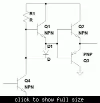
See diagram below - classic totem-pole output with drivers of same polarity at top and bottom. This is usually what is implied by the term.
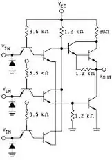
See diagram below - two for the price of one. Q1 & Q4 are a classic totem pole driver. Q2 & Q3 form a complementary push-pull output pair - less commonly implied by totm pole terminology.
The alternatives to a totem pole stage are -
A passive pullup (or pulldown) where a resistor is used to provide drive in one direction and is "pulled" in the other directionby an active device.
An "open collector" drive where there is an active device "pulling" in one direction and nothing pulling in the other. This allows users to add their own "pullup" which is the the "load fopr the active driver, and/or to connect a number of such stages in parallel with a single load shared by all.
Current source pullup. This is like using a passive resistive pullup but has somewhat different characteristics.
A totem pole
Provides active and so controlled and potentially high level and fast drive in both directions.
Has to be designed to avoid excessive (or any) "shoot through" current when both drivers are on at once. Whether this is an issue depends greatly on application and design.
Is "always on" either pulling up or pulling down or a bit of both.
Switches between on chip supply rails (say Vdd and Ground) so does not allow loads to be switched at voltages above supply rail.
A non totem pole design of one of the 3 main sorts has various pros and cons.
Totem pole tends to be faster switching.
Totem pole is not easily paralled with other similar devices to create 'wired OR" arrangements. Hi and low drivers fight each other. Opn collector devices do a much better job of this. Devices with internal R's or current sources can be combined with limitations.
TP has potential shoot though issues - others don't.
TP is limited to drive between power supply rails. Open collector/current source/resistor allow a voltage greater than IC stage Vdd to be switched.
Which type you should use depends on design aims.
TP is good for fast single output when due care is taken about what happens in the middle range between high and low.
Open collector is far better for paralleling. Resistor and current source (with sources or resistor inside IC) allow paralleling with compromises.
Generally a look at what needs to be achieved makes the choice reasonably clear.
Supercat notes:
The main point of totem pole drivers as used in the original TTL logic chips was to use all NPN transistors, but still provide at least some active pull in each high and low direction. Due to the difference in N and P carrier mobilities, NPN and PNP transistors are never truly symmetric, and there were advantages to using NPN.
In CMOS logic, the N and P channel drivers are symmetric and the driver designs are truly complementary (by definition since that's what the C in CMOS stands for). Since most logic is implemented with FETs instead of bipolar transistors nowadays, the old totem pole output driver topology of TTL logic is rarely used anymore.
Some other consideration about the use of push-pull stages:
The input capacitance is the one of two transistors, so in high-speed MOS technology you may want to use open-drain stages to halve the input capacitance, or input current for TTL stages.
Some bus like I²C use open-collector (open-drain) drivers to allow any device to take control of the bus by pulling the line low. It basically uses the principle of the wired OR.
It's a minor effect, but with push-pull stages you may have a time in which both the transistors are conducting, creating a direct path to ground. In resistor-transistor drivers this current will be limited by the resistor.