8

I'm using a PCB with some nixies on it.

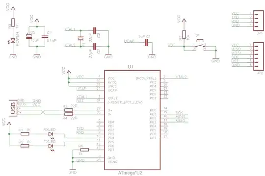
They are driven by the KD155IC, which is a clone of the SN7441. I run them on 175V with a 10k Resistor, should give them a working voltage of 145V, 3mA.

But a strange effect happens when cycling through numbers:

  1. Some numbers don't even display properly, the just produce some red-glowing something in the tube
  2. Some numbers display, but with a small or large blue glow behind them
  3. The rest display properly

Not working: 1 With blues-glow: 0,3,4,8,9 Normal: 2,6,7

Here are some images to understand what I talk about:

Nixie tube

Nixie tube

Nixie tube

What I tried so far

  1. Changed tubes to a set of "know-working" which run in another project for a long time No Effect
  2. Mounted the "not working" tubes into a "know-working" circuit WORK FINE!
  3. Changed several KD155 ICs No Change!
  4. Tested KD155 IC's on other circuit, WORK FINE!
  5. Changed power supply. No Change

Does anybody has an idea what could be the problem?

sgt_johnny
  • 809
  • 4
  • 11
  • What is the HV supply in the known working circuit? Did you *measure* the 10K? Blue is usually an indication of excessive current. – Spehro Pefhany Jun 26 '15 at 18:40
  • The HV Supply is in both circuit exactly the same model, a StepUp converter. 12-16V in, 150-200V out. I use many of these, so i don't think they make problems.... No i've not measured the 10k, but i will do that, maybe wrong ones were delivered – sgt_johnny Jun 26 '15 at 18:46
  • Don't laugh but also check the power supply is present on the driver chips. 10K seems on the low side to me, but there is no datasheet to consult. – Spehro Pefhany Jun 26 '15 at 18:56
  • Would the driver chips do anything without power supply? :O – sgt_johnny Jun 26 '15 at 18:58
  • Datasheet: http://www.tube-tester.com/sites/nixie/data/in-12a.htm They say Typical Plate voltage 145V, i use 175 so that makes 30V differce, current should be about 2.5 to 3.5 mA.... 30V/3mA is about 10k – sgt_johnny Jun 26 '15 at 19:01
  • They might because they could be getting partially powered through inputs. It would make for a messy display. – Spehro Pefhany Jun 26 '15 at 19:02
  • Sorry, but I can't get this out of my head. It may be the time of year, but is it _just_ possible that they're _pixie_ tubes? – Transistor Dec 24 '15 at 23:39

1 Answers1

3

Firstly, max ignition voltage for the IN-12 is 170V so you are cutting it a little close with the 175V supply, but depending on the converter i'd say that probably won't be an issue.

What i do suspect from your images, though, is that you have switched (or somehow shorted?) your connections between the grid and the 1-cathode, leading to the 1-cathode acting as your anode instead of your grid.

If i am reading your images correctly, you can see the grid lead glow orange when you try to display the one, and the blue glow (typically associated with the anode) appears to be emanating from your 1-cathode.

Brog
  • 1,002
  • 6
  • 11