5

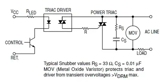
I'm interfacing the BT139-600 TRIAC with this MOC3051-M Opto-triac. I want to build a snubber circuit for the TRIAC as shown in the MOC3051M opto-triac's datasheet @ page 8, figure 12.

snubber circuit

The load will be a 230V AC, 4A motor. What are the recommended characteristics of the Rs, Cs and MOV in that schematic (the type of the resistor and capacitor, power specifications, voltage limits)? Would this components be a good pick for the snubber?

Cs: Ceramic Capacitor 10nF

Rs: 33 Ohm 5W wirewound resistor

MOV: JVR14N431K 275V AC MOV Varistor

Do I also need a snubber for the triac driver?

m.Alin
  • 10,638
  • 19
  • 62
  • 89
  • 1
    Please specify load characteristics and use of circuit. Ideally a circuit diagram. The snubber's role is to dissipate transient energy which is looking for a home at switch off time. We need to know how much energy is there and how it is "stored" to know what sort of home it needs. As a guide you want an energy sink that will stop reactive voltage rising dangerously high, that will dissipate available ractive energy prior to the next switching cycle and which has minimal possible effect the rest of the time. Not magic, just compromise. – Russell McMahon Aug 03 '11 at 02:09
  • I've updated my question, so that it would be more clear. – m.Alin Aug 21 '11 at 12:02
  • Wouldn't a 10nF capacitor quickly be charged up to the MOV clamping voltage, by the inductance in the electric motor? 10nF at 430V is 924 millijoule. For this cap to hold the energy of the motor inductance, said inductance must be less than ~ 100uH. Is it? – avl_sweden Jul 21 '15 at 20:43
  • 1
    @avl_sweden, the triac won't switch off until the motor current has fallen to near-zero. Then the concern becomes dV/dT as the voltage across the triac jumps to the line voltage. – Technophile Oct 24 '15 at 15:56

1 Answers1

4

Please specify load characteristics and application. Very desirably provide a circuit diagram or at least a good word picture.

The snubber's role is to dissipate transient energy which is looking for a home at switch-off time. We need to know how much energy there is, and how it is "stored" to know what sort of home it needs. As a guide you want an energy sink that will stop reactive voltage rising dangerously high, that will dissipate available reactive energy prior to the next switching cycle and which has minimal possible effect the rest of the time. Not magic, just compromise.

Note that as your chosen optocoupler is "random phase switchable, you will have greater need of a snubber than if you were zero crossing switching - subject to the usual warnings re effects of inductive load currents not being zero at zero voltage.

To "start you on your way" ...

stevenvh
  • 145,145
  • 21
  • 455
  • 667
Russell McMahon
  • 147,325
  • 18
  • 210
  • 386
  • The first link, AN437, isn't valid. – m.Alin Aug 21 '11 at 12:04
  • 1
    @m.Alin - fixed! – stevenvh Aug 21 '11 at 12:18
  • "subject to the usual warnings re effects of inductive load currents not being zero at zero voltage" But the the current will be zero at turn-on and the thyristor will turn off only after the current (not voltage) drops to zero or am I missing something? – jpc Aug 22 '11 at 21:49
  • 2
    For very inductive load you do not want it turning on at zero voltage, as that corresponds to max current. Instead you want to turn on at maximum voltage. (Remember inductive loads cause current to lag voltage) – ljbade Apr 24 '13 at 09:10