3

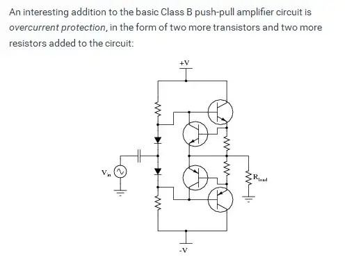
I'm looking to increase the output current drive of a high voltage op amp using a push pull amplifier. The OPA454 datasheet includes an application circuit to do exactly this, and includes some current limiting resistors:

enter image description here

As noted, \$R_3 = 20\Omega\$ provides current limiting and allows the op amp to drive the output when \$|V_O| < 0.7\$V (i.e. both transistors are off). I understand that \$R_3\$ provides current limiting by stealing the op amp's output current from the transistor that is on. But how do I choose the value of \$R_3\$ to set the current limit to a particular value \$I_{\text{MAX}}\$ (e.g. \$2.5\$A)? \$I_{\text{MAX}}\$ doesn't have to be too exact, it just needs to be in the desired range (e.g. \$\pm 250\$mA).

Also, how do I choose the values of the emitter degeneration resistors \$R_4\$ and \$R_5\$? I know they are used to prevent thermal runaway by reducing \$V_{BE}\$ (and thus \$I_C\$), but I think they will also affect \$I_{\text{MAX}}\$ because they will affect the voltage across \$R_3\$.

The purpose of this circuit is to generate an adjustable output voltage from about \$0\$V to \$+100\$V with \$I_{\text{MAX}} \approx 2.5\$A. I've got dual but unbalanced supplies (not the \$\pm 50\$V shown) to support the output voltage range. Based on the suggested transistors in the above application circuit, I will probably use the MJ15003/MJ15004. Frequency response is not a huge concern since the output has milliseconds to transition.

I would guess that the relevant specs for determining the resistor values are the op amp max output current and transistor \$h_{\text{FE}}\$ (the former affects the maximum \$I_B\$, which is multiplied by \$h_{\text{FE}}\$ to set the maximum \$I_C\$), but is there anything else I need to take into account?

Alternatively, is there a better way to limit the output current for this push-pull amplifier?

Null
  • 7,448
  • 17
  • 36
  • 48
  • I think you might be confusing the role of R3. The circuit you have does not include a mechanism to limit the output current supplied to the load. R3 is only there to limit/protect the opamp's output as per Andy Aka's answer below. If you want to have a current limit you'll need add a current sense resistor and a separate control circuit for that. – Jon Jun 25 '15 at 17:26
  • @Jon I think I see what you're saying. Please see my clarification question in my comment to Andy's answer. And feel free to post your comment as an answer so I can potentially upvote and/or accept it. – Null Jun 25 '15 at 17:59

1 Answers1

5

The current from an OPA454 is just about limited to a little over 100 mA and on a good day you might get 150 mA so, R3 is chosen to prevent the OPA454 from producing this current i.e. the BJTs take over at a certain point and produce the bulk of the output current.

For instance, at 100mA drive through R3 (20 ohms) the Vbe across one of the transistors is aiming be 2V. Clearly it can't so this means the transistors are doing their job of relieving the op-amp of having to perform too hard.

Basically, if R3 is 20 ohms and the transistors start to turn-on at (say) 1V, the peak current taken from the OPA454 is 50mA and well within the spec of the device. Remember the OPA454 cannot produce watts of power - you can't expect it to deliver 50V from a 100V rail driving 100mA - it will burn long before then.


EDITED BELOW

Here is a typical push-pull output stage that uses two more BJTs for inhibiting the drive current supplied by the output transistors: -

enter image description here

Taken from AllAboutCircuits useful site on push-pull amplifiers. Because the original circuit uses both bases connected together, to make this work requires maybe a 10 ohm resistor inserted in each base - basically replacing each diode in the above diagram. The pull-up and pull-down resistors are not needed.

If an emitter resistor is 0.5 ohms, at round about 2A current there will be enough voltage across it to turn on the extra transistor and this diverts base drive away from the main transistor.

Here's what it looks like in a simpler form (a clsss A single BJT driver): -

enter image description here

Taken from the Analog Devices Wiki website. You might also have seen this method used in controlling the current thru an LED: -

enter image description here

clabacchio
  • 13,481
  • 4
  • 40
  • 80
Andy aka
  • 434,556
  • 28
  • 351
  • 777
  • Ah, so you're saying R3 is intended to reduce the output current demanded of the op amp by the *transistor* for its base current, not the current demanded by the *load*? The output current demanded of the op amp by the load itself is reduced by the push-pull amplifier itself -- that's the whole point of it. – Null Jun 25 '15 at 17:54
  • @Null for small output levels (i.e. less than one base-emitter volt drop) the op-amp supplies the load current thru R3. If the load demands 30mA then R3 doesn't quite start turning the relevant transistor on because 30mA x 20R = 0.6 volts. If the load demands more current the relevant transistor starts to turn on and it (the transistor) supplies the bulk of current to the load. – Andy aka Jun 25 '15 at 18:08
  • If you used something like LTSpice you'd be able to see the effects of the emitter resistors BTW. – Andy aka Jun 25 '15 at 18:10
  • I understand that the op amp supplies the load current through R3 when both transistors are off. That's the only point to R3? If I removed R3 the amplifier would work as before except for an introduction of crossover distortion for \$|V_O| < 0.7\$V? – Null Jun 25 '15 at 19:44
  • Cross over distortion would barely happen at low/medium frequencies because the closed-loop feedback from the output will force the op-amps to rapidly move thru the tradional cross-over region. t higher frequencies you would see evidence of course. – Andy aka Jun 25 '15 at 21:03
  • I'm playing with an LTspice sim using a comparable high voltage amplifier set to unity gain, and somewhat similar transistors. Vin is set to a constant voltage (e.g. 15V), and I ramp the load current from 0 to 3A. The output voltage is stable at Vin until the op amp output current reaches its maximum value, after which the output voltage collapses. Increasing the emitter resistors and/or decreasing R3 causes this to occur at a lower load current because the op amp output current ramps up to its max at a lower load current. This makes sense to me. – Null Jun 25 '15 at 21:13
  • I don't trust the sim beyond the op amp max output current, but the question now is what would happen if the load tries to draw more current than the op amp can provide to R3 and the transistors? The load voltage collapses but the load current increases as demanded by the load? – Null Jun 25 '15 at 21:15
  • @Null - in that situation it is just a thermal issue - if your transistors are unable to deal with the heat they will need to dissipate your circuit will fail catastrophically (smoke). If they can then the output voltage will just collapse (the amount depends on the output transistor characteristics) until the load is removed. Clearly you want to size everything so this does not happen under normal conditions. – Jon Jun 25 '15 at 21:35
  • @null regarding your sim I believe that the output transistors were emanding too Mich base current due to their limited Hfe. You could try output devices with a higher Hfe. Regards overall current limiting I'd consider having this functionality in the power supply but there are several circuits on line that use two more transistors monitoring the voltage across the emitter resistors to shut down each output device. – Andy aka Jun 26 '15 at 08:04
  • @Andyaka The power supply will be powering other circuits so I'd like this circuit to limit its own current. I've seen the scheme with the two extra transistors to steal base current from the power transistors -- I think this is also how R3 is "limiting" the current, albeit with a linear I-V relationship instead of an exponential with the added transistor. I was hoping R3 would be a simple way to limit the current, but it's probably best to use the transistors. I'm going to add some circuitry to disconnect the load when the current reaches a certain threshold, too. – Null Jun 26 '15 at 20:51