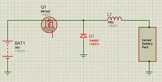
I've got a circuit I'm developing using an op amp to drive a power MOSFET for an electronic load:
I'd like to test it for stability, but I don't have enough experience to know what perturbations are most likely to show any instabilities.
I have the following ideas:
Inject a square wave (offset such that low value is >= 0V) into the non-inverting input while monitoring the voltage on the sense resistor (load current waveform). This would simulate sudden changes in the control voltage (1V/A) likely to be supplied later by a DAC.
Apply stepped input voltage to IN+, simulating connection of power supply under test.
Are these sensible ideas that are likely to uncover any op-amp related instabilities?
Also, are there LTSpice simulation exercises that might be worth trying?
UPDATE:
- I revised the schematic to be more suitable for simulation. I found and used models for the specific parts I'm using and removed all compensation elements for a baseline simulation.
- I ran an analysis feeding a DC-offset square wave into the control pin (non-inverting input in this circuit). The result was dead stable. There's a teeeny-weeeny 1mV overshoot on the rise if you zoom way in, otherwise it absolutely mirrors the input (except it represents current flow of course). I even reduced the rise time to 1ns to see if I could get it to ring, but no luck :)
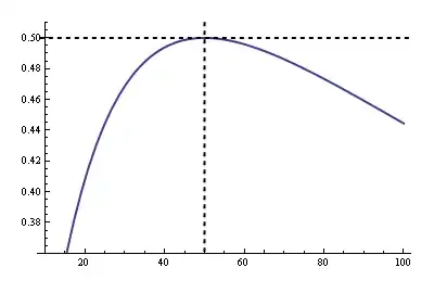
I ran an .AC analysis like @Kevin White suggested, and found a 62 degree phase margin in the open loop gain.
I built it up as @mkeith suggested, and unfortunately it oscillates like crazy on the breadboard :) I was able to make some progress stabilizing it a bit until I accidentally blew out my MOSFET. It's down to the store tomorrow to get a new one so I can carry on from there :)