22

I have a microcontroller (PICAXE 20X2) and a pot meter. I programmed the micro so that it sends any change of pot meter to serial port of PC. Obviously it is a 8bit ADC. Now the interesting thing for me is being able to decode this serial data on the oscilloscope.

Here are two pictures, the first is when the micro is sending "0" to PC and the next one is when it sends "255". The data is being transmitted using 9600 buad and I can receive them at the PC terminal.

First Pic enter image description here

Second pic enter image description here

So my question is, did I capture the right data on my scope, and second how one can read and decode this pulses into a hex or ascii format. I mean how to read this rising and falling pulses (0/1).

Thanks.

Dumbo
  • 3,244
  • 14
  • 44
  • 69
  • 3
    serial lines idle in the logical '1' state, so be aware you have 1 on the bottom and 0 on the top here. I know people have already locked onto that. My comment is for the purpose of guiding future scope-grabs of serial data; you can probe things so that the idle state is high. – JustJeff Jul 31 '11 at 16:33

3 Answers3

15

First something Olin noticed as well: the levels are the reverse of what a microcontoller usually outputs:

enter image description here

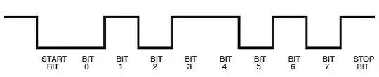
Nothing to worry, we'll see that we can read it this way too. We just have to remember that on the scope a start bit will be a 1 and the stop bit 0.

Next, you have the wrong time base to read this properly. 9600 bits per second (more appropriate units than Baud, though the latter isn't wrong per sé) is 104\$\mu\$s per bit, which is 1/10th of a division in your current setting. Zoom in, and set a vertical cursor at the first edge. That's the start of your start bit. Move the second cursor to each of the next edges. The difference between the cursors should be multiples of 104\$\mu\$s. Each 104\$\mu\$s is one bit, first the start bit (1), then 8 data bits, total time 832\$\mu\$s, and a stop bit (0).

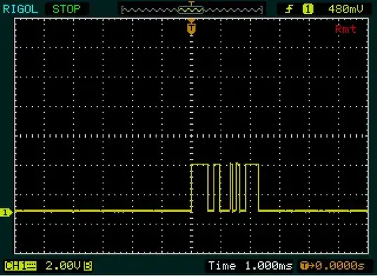
It doesn't look like the screen data matches the sent 0x00. You should see a narrow 1 bit (the start bit) followed by a longer low level (936\$\mu\$s, 8 zero databits + a stop bit).
Same for the 0xFF you're sending; you should see a long high level (again 936\$\mu\$s, this time the start bit + 8 data bits). So that should be nearly 1 division with your current setting, but that's not what I see.
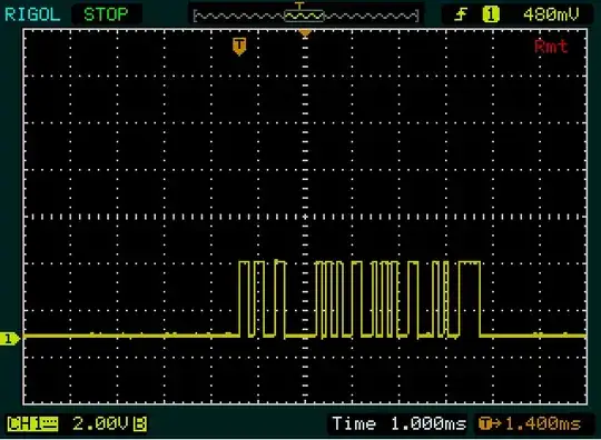
It looks more like in the first screenshot you're sending two bytes, and in the second four, with the 2nd and 3rd the same value.

guesstimates:

0b11001111 = 0xCF
0b11110010 = 0xF2

0b11001101 = 0xCD
0b11001010 = 0xCA
0b11001010 = 0xCA
0b11110010 = 0xF2

edit
Olin is absolutely right, this is something like ASCII. As a matter of fact it's 1's complement of ASCII.

0xCF ~ 0x30 = '0'
0xCE ~ 0x31 = '1'
0xCD ~ 0x32 = '2'
0xCC ~ 0x33 = '3'
0xCB ~ 0x34 = '4'
0xCA ~ 0x35 = '5'

0xF2 ~ 0x0D = [CR]

This confirms that my interpretation of the screenshots is correct.


edit 2 (how I interpret the data, upon popular request :-))
Warning: this is a long story, because it's a transcript of what happens in my head when I try to decode a thing like this. Only read it if you want to learn one way to tackle it.

Example: the second byte on the 1st screenshot, starting with the 2 narrow pulses. I start with the second byte on purpose because there are more edges than in the first byte, so it will be easier to get it right. Each of the narrow pulses is about 1/10th of a division, so that might be 1 bit high each, with a low bit in between. I also don't see anything narrower than this, so I guess it's a single bit. That's our reference.
Then, after 101 there's a longer period at low level. Looks about twice as wide as the previous ones, so that could be 00. The high following that is again twice as wide, so that will be 1111. We now have 9 bits: a start bit (1) plus 8 data bits. So the next bit will be the stop bit, but because it's 0 it's not immediately visible. So putting it all together we have 1010011110, including start and stop bit. If the stop bit wouldn't be zero, I would have made a bad assumption somewhere!
Remember that a UART sends the LSB (least significant bit) first, so we'll have to reverse the 8 data bits: 11110010 = 0xF2.

We now know the width of a single bit, a double bit and a 4 bit sequence, and we have a look at the first byte. The first high period (the wide pulse) is slightly wider than the 1111 in the second byte, so that will be 5 bits wide. The low and the high period following it each are as wide as the double bit in the other byte, so we get 111110011. Again 9 bits, so the next one should be a low bit, the stop bit. That's OK, so if our guesstimating is correct we can again reverse the data bits: 11001111 = 0xCF.

Then we got a hint from Olin. The first communication is 2 bytes long, 2 bytes shorter than the second. And "0" is also 2 bytes shorter than "255". So it's probably something like ASCII, though not exactly. I also note that the second and third byte of the "255" are the same. Great, that will be the double "5". We're doing fine! (You have to encourage yourself from time to time.) After decoding the "0", "2" and "5" I notice that there's a difference of 2 between the codes for the first two, and a difference of 3 between the last two. And finally I notice that 0xC_ is the complement of 0x3_, which is the pattern for digits in ASCII.

stevenvh
  • 145,145
  • 21
  • 455
  • 667
  • Thanks for tips, I will try to capture the right waveform and update my question. – Dumbo Jul 29 '11 at 12:55
  • Thanks, Would you mind marking the picture like how you find those data? – Dumbo Jul 31 '11 at 14:40
  • 1
    @Sean87 - It's become a long story, I added it to my answer. It illustrates my way of doing this, other may follow different paths. Don't worry if you think you wouldn't have seen half of it; most of it is just experience and imagination. There's no special intelligence involved. – stevenvh Jul 31 '11 at 15:26
  • Very nice answers and question, but i'm wondering why you said that the Oscilloscope shows the reversed of what actually is. I know that the idle line is almost always high, but isn't the oscilloscope supposed to capture an exact image of the real thing? Except if the user changed a parameter of the oscilloscope's settings. – KeyC0de Mar 15 '16 at 09:22
7

Something isn't adding up. Your signals appear to be 3.3V peak to peak, which implies they are straight out of the micro. However, microcontroller UART levels are (almost) always idle high and active low. Your signals are inverted from that, which isn't making sense.

To ultimately get this data into a PC, it has to be converted to RS-232 levels. This is what a PC COM port expects to see. RS-232 is idle low and active high, but low is below -5V and high is above +5V. Fortunately there are chips for that which make it easy to convert between typical microcontroller logic level UART signals and RS-232. These chips contain charge pumps to make the RS-232 voltages from your 3.3V power supply. Sometimes these chips are referred to generically as "MAX232" because that was a part number for a early and popular chip of that type. You need a different variant since you are apparently using 3.3V power, not 5V. We make a product that is basically one of these chips on a board with connectors. Go to http://www.embedinc.com/products/rslink2 and look at the schematic to see one example of how to hook up such a chip.

Another thing that doesn't add up is that both sequences appear to be more than one byte, even though you say you are only sending 0 and 255. This type of serial data is sent with a start bit, then the 8 data bits, then a stop bit. The start bit is always at the opposite polarity from the line idle level. In most descriptions, the line idle level is refered to as "space" and the opposite as "mark". So the start bit is always at mark. The purpose of the start bit is to provide time synchronization for the remaining bits. Since both sides know how long a bit is, the only question is when the start of a byte is. The start bit provides this information. The receiver essentially starts a clock at the leading edge of the start bit, and uses that to know when the data bits will be coming along.

The data bits are sent in least to most significant order, with mark being 1 and space being 0. A stop bit at the space level is added so that the start of the next start bit is a new edge, and to leave a little time between bytes. This allows for a little error between the sender and receiver. If the receiver were slower than the sender even a little bit, it would otherwise miss the start of the next start bit. The receiver resets and starts its clock anew each new start bit, to timing errors don't accumulate.

So from all this you should be able to see that the first trace appears to be sending at least two bytes, and the last looks like maybe 5.

It would help if you expanded the time scale of the traces. That way you could measure what a bit time really is. That would allow you to verify you really have 9600 baud (104 µs/bit), and let you decode individual bits of a capture. As it is now, there isn't enough resolution to see where the bits are, and therefore actually decode what is being sent.

Added:

It just occurred to me that your system may be sending the data in ASCII instead of binary. That's not how it's generally done since converting to ASCII in the little system takes more of the limited resources, uses bandwidth poorly, and it's easy to do the conversion on the PC if you want to display the data to a user. However, if your transmissions are ASCII characters that would explain why the sequences are more than one byte, why the second one is longer ("255" is more characters than "0"), and why both appear to end in the same byte. The last byte is probably some sort of end of line character, which would usually be a carriage return or a line feed.

Anyway, expand the time scale and we can decode exactly what it being sent.

Olin Lathrop
  • 310,974
  • 36
  • 428
  • 915
  • 1
    The stop bit (and it being opposite of the start bit) also forces an edge at the start of a new transmission. – stevenvh Jul 29 '11 at 13:16
  • @steven: Yes, I realized that I left that out upon re-reading my answer and added it in a edit, probably at the same time you were writing your comment. – Olin Lathrop Jul 29 '11 at 13:39
  • What's that they say? Great minds think alike? :-) – stevenvh Jul 29 '11 at 13:48
  • 4
    While sending ASCII is "inefficient" it can still be a very good choice. Most of my embedded systems not only send ASCII, they receive ASCII commands as well, making it possible to manually experiment by "having a conversation" with them from a terminal program. The SCPI standard (sort of an improvement on GPIB, extended to other electrical interfaces) is a very formal method that works along these lines. – Chris Stratton Jul 29 '11 at 18:47
  • @Chris: Yuk. ASCII is a pain for a little system. perhaps yours are larger embedded systems that run a OS, but on small micros ASCII is a big waste and a inconvenience. Yes I understand you can talk to it directly with Hyperterm or the like, but we usually make a test program that runs on the PC and provides a command line interface to the low level binary protocol. That pushes the conversion to fluffy user units onto the PC where it belongs, especially if your small system eventually needs to communicate with another small system. – Olin Lathrop Jul 29 '11 at 20:52
  • 4
    Going to *strongly* disagree. Ascii takes such a tiny amount of code, even running bare metal on a little 8-bitter. Sure, you can write a custom program, but what happens 10 years from now when that's lost and it would take a virtual machine to run it even if it could be found? And sure, any programmer worth his salt can hack up a binary terminal to reverse engineer something. But human readable interfaces are well worth the small overhead in most but the most severely memory limited and performance critical systems. Plus if you have the memory, you can embed debug output with an on/off. – Chris Stratton Jul 29 '11 at 21:20
  • 2
    I should mention that i got started on the ASCII interfaces as it was a customer's requirement... but I kept them because of how useful they are. I could add an idea as a command in the firmware and then test it anywhere in the facility. _Without_ having to deploy an update to the configuration client every time I posted an experimental firmware version with extras for looking into a problem someone was having in a complicated system of which it was but one module. On the phone with a client, I could have them fire up a terminal and walk them through using unpublished factory test functions. – Chris Stratton Jul 29 '11 at 21:23
  • As I understood from PICAXE 20X2 datasheet, it uses soft RS232 communication, I am not sure how it works, but I am able to send ASCII into chip and also data comes out as ASCII. This chip also has two HARDWARE serial pins that are "hserout" and "hserin". I think if I am going to use them, then I have to user something like MAX232. So I think as most of you said my scope was capturing ASCII data. I had no time yet to use suggested timings on the scope. But it is not possible to decode the ASCII code just from the pictures above? Thanks. – Dumbo Jul 31 '11 at 14:38
1

You need to know the full details: the speed, if there is there a start bit, the number of data bits, if there is a stop bit and if there is a parity bit. This should be a function of how the UART in the microcontroller is configured.

If the Rigol scope doesn't have a serial decode option (many DSOs do) you can use X-cursors to aid in the decoding. Place the first cursor at the leading edge of the data and move the second cursor through the bitstream. The delta between the cursors can be used to determine which 'bit' you're currently hovering over by simple arithmetic. Ignore start/stop/parity bits, obviously.

Adam Lawrence
  • 32,921
  • 3
  • 58
  • 110
  • There is always a start bit and always at least one stop bit. There may be extra stop bits, but these are indistiguishable from dead time between bytes. Old mechanical decoders sometimes needed two stop bits to allow time for the mechanism to reset. Nowadays there are almost always 8 data bits and no parity bit, but as you say, that can vary. – Olin Lathrop Jul 29 '11 at 13:48