2

I am currently using TPS61240 as a boost converter for my project. As i did not have any sample previously so there was no way I could test it. I ordered the IC and placed it on my final PCB directly. PCB layout and external components are according to the datasheets. I ran continuity and input voltage measurement test. There is no problem in PCB and Input voltage. But I am not getting 5 volts from the IC. I am in great trouble. Any suggestion would be appreciated. Thanks in advance.

Here is the PCB layout.

enter image description here

and here is the Schematics

enter image description here

Arjun
  • 680
  • 5
  • 24

2 Answers2

3

I see two problems.

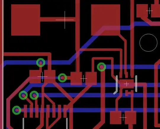
  1. You say you are using a 1206 type inductor in your comments, but the pad connected to pin 5 on your PCB is HUGE, at least for an inductor 4 or maybe 6 times as large as that. Unless that's not an inductor, but a smoothing cap, which would be a problem in itself, because that's where the inductor should be.
  2. At first I was sure you weren't placing/connecting things right, but now I'm thinking you are connecting pin 4 and 6 (EN and Vin) in a rather round-about way through the big component that's either wrong or your inductor. If the Vin at least has a cap close, that may be okay, but it's not the neatest. If there's no cap near Vin with simple tracing for the power in, it'll probably choke on the trace inductance or resistance or some such.

Which leads me to wonder: Are you sure you placed the pins in the package in the right order?

If you did and you got confused about the inductor you are using: Solder a decent cap directly onto the Vin pin with a strong connection to the ground trace. With a booster that needs only 1uH you need to be very wary of any trace inductances and resistances. Also maybe beef up the ground trace (and Vin trace) with some solder or copper wire.

Asmyldof
  • 18,299
  • 2
  • 33
  • 53
  • To your first response, Yes inductor pad is huge, but i did place it carefully and i am 100% sure about my connection, Originally i had thought about using a big inductor with greater current capacity, but as the boost converter is itslef limited to 450ma, i thought i could replace it with smaller inductor. now i am using fixed value, 1uh , 1.075a current capacity inductor. – Arjun Jun 15 '15 at 11:23
  • To your second response, there is a 0805 capacitor to near VIN (just left to it, near the first closet via), is that causing the problem here?? – Arjun Jun 15 '15 at 11:27
  • @Arjun There is a "huge" loop there. It's tiny compared to your finger, but in the world of 3.5MHz that might well be an inductance big enough to decrease the efficacy of that capacitor. Vin and Vout caps should be as close to a switching regulator as physically possible, especially at frequencies above 250kHz. – Asmyldof Jun 15 '15 at 11:31
  • Thanks for your response, I have designed a new board just for boost converter, i guess i have removed that 'huge loop' thing. i will let you know if i get it right. :D – Arjun Jun 15 '15 at 12:32
  • @Arjun Why _immediately_ design a new board? Use a capacitor and bodge wires, unless you want to keep debugging by making PCBs until you're 5 designs in. What if it works, but your ripple needs a different cap to become acceptable? Just try some stuff with an oscilloscope. – Asmyldof Jun 15 '15 at 12:48
  • I have tried everything i could and I didn't get any clue, I measured the voltage at input side, its 2.7 voltage, every pins are connected, output voltage is zero volt. Boost IC Package is WSON, and i dont have any equipments like Oscilloscope. So its practically impossible for me to run advance test. Thank you – Arjun Jun 15 '15 at 13:33
  • What kind of capacitor should i use? – Arjun Jun 15 '15 at 14:30
  • @Arjun If you don't know that for sure yet, definitely don't start designing boards left and right. I'd start with what the datasheet tells you to: a 2.2uF MLCC across Vin and GND; 4.7uF solid tantalum, or possibly MLCC (likely going to be okay) across Vout and GND - Close to the chip!. For designs like these it is very important that you read and understand the operation and application guidelines, in this case: http://www.ti.com/lit/ds/symlink/tps61240.pdf - pages 9 and up – Asmyldof Jun 15 '15 at 15:00
  • I have already gone through the datasheets. I have strictly followed the datasheet(except for layout). I am in great trouble i guess :D – Arjun Jun 15 '15 at 15:51
  • I designed a new PCB with capacitors and inductors very close to the IC. This time I am getting output voltage exactly equal to input voltage. What may be the problem? – Arjun Jun 16 '15 at 07:17
3

I have added a 6.3V 100uf capacitor parallel to the 4.7uf ceramic capacitor at the output of the BOOST converter IC. Now Its working fine, and I am able to get 5.22 voltage from the input 3.3v.

Arjun
  • 680
  • 5
  • 24