I am trying too get my first (ever) servo sweeping back and forth and for some reason am having enormous difficulty with the wiring.
In the Fritzing pic below, I have the circuit connected (both + and - terminals) to a 5V power source (Arduino). The orange "signal" (or "pulse") line is connected to an output pin on the Arduino. Because, for reasons you'll see next, I'm convinced this is a wiring issue and not and Arduino/code issue, I've omitted the Arduino from the diagram/pic for simplicity's sake.
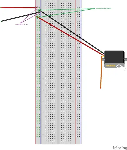
When I power this on, nothing happens. At first I thought it was a code issue, but then I busted out my multimeter, setting it to its 6V setting. In the pic above, you'll see two contact points in purple; these are the board connections to the Arduino's 5V and GND connectors respectively. When I test them with the multimeter, they do in fact read about 5V. So far so good.
However, when I test the green connections in the pic above (the power connections between the breadboard and the servo), the multimeter tells me that there is -20V (that's negative 20V) passing through the servo!?!?
I may very well have a code issue, but this is certainly not correct either. Am I wiring this up wrong, if so, how? If everything looks OK, what are my next steps for debugging/troubleshooting here?