7

Looking for a simple design to convert from 4-20mA signals to 0-3V3, I'm thinkin about configuration shown at picture attached. enter image description here And I would like to discuss its suitability.

It is based on: - A follower configuration for a Rail-to-Rail OpAmp, powered at 3V3. - A 165Ohm resistor to get, 3V3 at 20mA, and 0V66 at 4mA.

What do you think about? It is any improvement I can do? Or it would be better to work with another more precise configuration?

  • It is thought for a low power applications (<5V), but it would like to know if it could work with 4-20mA transmitters powered at 24V too.
Yolco
  • 367
  • 1
  • 5
  • 13
  • If you power the op-amp with > 3.3V you don't need the positive rail in the input or output ranges. Depending on what comes next (microc-controller?) you might not even need 0-3.3V. – Wouter van Ooijen Jun 12 '15 at 14:55

3 Answers3

5

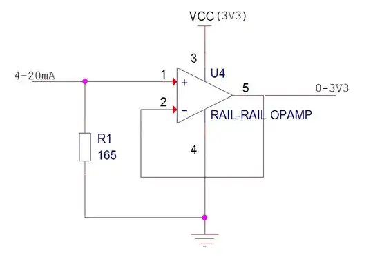
It will work. You might want to use a somewhat lower value of resistor so you can detect overrange on the 4-20mA. The offset zero allows you to detect underrange (this is useful for sensor break detection and such like). Of course you lose a bit of resolution on the ADC- 20% on the bottom. You could also use a stage with some gain rather than a voltage follower which would allow an even lower resistor (say 49.9 ohms) to be used and would allow a better performance op-amp to be used (relaxing the requirements to input common mode range includes ground and R-R on the output only).

Take care as to the layout- use Kelvin connection to the sense resistor, especially if you want to have a high accuracy (< 0.1%) circuit and are using a lower value resistor.

The compliance of the transmitter will determine the minimum supply voltage, and your 3.3V subtracts from that, so a lower input voltage is desirable, however too low and you lose accuracy. If several devices are connected in series on the loop then 12v or even 24V may not be enough (the transmitter may require 10V, an indicator another 10V and your circuit 3.3V is getting close even at 24V).

Note that a short across the transmitter will damage the input resistor most likely and probably blow the *** out of the op-amp and likely other stuff too. This can be protected against, at some cost in input voltage and parts. If you put a series resistor on the op-amp inputs it may limit the damage to just the input resistor.

Spehro Pefhany
  • 376,485
  • 21
  • 320
  • 842
  • How does would current loop work with several devices in series? – Andy aka Jun 12 '15 at 13:26
  • @Andyaka If they're loop-powered (as are most indicators- only two wires) or galvanically isolated it works very well indeed- same current through everything in the loop. If not, well.. – Spehro Pefhany Jun 12 '15 at 13:40
  • Hmmm current sources in series LOL – Andy aka Jun 12 '15 at 13:54
  • Not sources.. receivers in series. Obviously exactly one transmitter. One or more power supplies. – Spehro Pefhany Jun 12 '15 at 14:41
  • Adding an 1kOhm input resistor on the OpAmp, will be enough to protect it without modifying the input conditions? I have some doubts about relaxing the input common mode range and the R-R, what did you mean about it? – Yolco Jun 16 '15 at 07:47
  • The other option I was thinking about has some gain, and high accuracy. But it needs a power source, in this case 24V, although it could be another voltage if resistors are modified. [Alternative Circuit](http://www.edaboard.com/attachments/116967d1430321852-4-20ma_to_0-3v3_ps24v.jpg) – Yolco Jun 16 '15 at 08:10
  • You have to read the datasheet of the op-amp to see what input current or voltage it can withstand (and to see what error resistor(s) will add). As to the input common-mode range, if you power an op-amp follower from 3.3V the inputs must be rail-to-rail (R-R) but if the op-amp has a gain of (say) 2 then the inputs only need to work from 0V to 1.65V (the output still has to swing 0V to 3.3V). More (and better performance and price/performance) op-amps are available that do that. – Spehro Pefhany Jun 16 '15 at 12:33
4

would like to know if it could work with 4-20mA transmitters powered at 24V too.

Yes, even though a 4/20 mA transmitter may be powered at a much higher voltage it is the current that flows through the device that determines the voltage across the 165 ohm resistor.

Think of a device that controls the current through its terminals - it is connected in series with a 24V battery. Ov of the battery connects to your monitor 0V and the device feeds the input to your circuit producing a current between 4mA and 20mA.

If the device were powered from 20,000 volts DC (impractical of course), would you see a current that is any different? No, because the device controls the current that feeds the 165 ohm resistor.

Andy aka
  • 434,556
  • 28
  • 351
  • 777
  • You are right. I explained myself too badly. I should explained it better. I ask it for two reasons: 1- If the circuit will be suitable to work and protect OpAmp and MCU of overvoltage, due to they are powered at 3V3 (also overvoltage issues, etc). 2- And because I would like to not need to add a DC-DC boost converter to power the transmitter (it should have its own source). – Yolco Jun 16 '15 at 07:55
  • OK I understand but have you got your answer? – Andy aka Jun 16 '15 at 08:54
4

First, that will not give 0V out at 4mA. It will deliver 0V at 0mA. For the full span, you will get your 3.3VDC out.

As for will it work with 24V powered 4-20mA transmitters... yes. It would work with 48VDC powered transmitters as well, as long as you sink the 4-20 signal to the transmitter common. a 4-20mA loop is 4-20mA; it doesn't matter what voltage is driving it.

Your circuit would not work if it is not the least receiver in a string however. It is common for 4-20mA loops to place the transmitter in series with several receivers. For that reason, most receivers use a simple sense resistor to pass the loop, and a differential amplifier reading across the sense resistor.

R Drast
  • 4,145
  • 15
  • 18
  • Thanks. The desired output will be 0V66-3V3 (4-20mA), and 0V for failure. The revceiver is the least, and it is connected to a MCU. So, the other point is to protect the MCU from overvoltages. – Yolco Jun 16 '15 at 07:15