I got a screw terminal with the following pin configuration:
X1
+-------------+
| (X) (X) (X) |       1 = 24V    2 = SIGNAL    3 = 0V
|  |   |   |  |
+--|---|---|--+
   1   2   3
My "requirements":
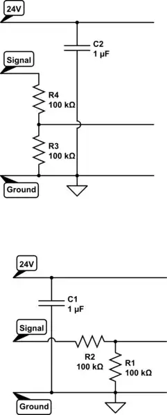
- Convert 24V SIGNAL to 12V logic
- Add bypass capacitor for supply
At the moment my schematic looks like this:
I need the design as compact as possible but I don't want to confuse myself in future.
What do you think: is the above schematic easy understandable or is it already too complex? And what is commonly more important in a schematic: simplicity or sheet "space"?